
Infrared remote control is a wireless, non-contact control technology with strong anti-interference ability, reliable information transmission, low power consumption, low cost, easy implementation, etc. It is widely used by many electronic devices, especially household appliances, and more and more More applications in computers and mobile phone systems. This paper first introduces the basic principle of the infrared remote control module. Secondly, it explains the working principle of the infrared remote control module. Finally, it introduces the important links and applications of the infrared remote control.
The basic principle of infrared remote controlThe infrared remote control transmitting circuit uses infrared light emitting diodes to emit modulated infrared light waves; the infrared receiving circuit is composed of infrared receiving diodes, triodes or silicon photo cells, which convert infrared light emitted by the infrared emitter into corresponding electric signals, and then send them Set the amplifier.
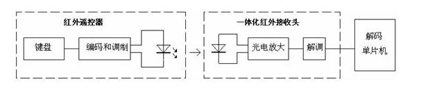
The transmitter is generally composed of an instruction key (or an operating lever), an instruction encoding system, a modulation circuit, a driving circuit, and a transmitting circuit. When the command key is pressed or the joystick is pushed, the command encoding circuit generates a desired command code signal, and the command code signal modulates the carrier wave, and then the power is amplified by the drive circuit, and then the modulated circuit code is externally transmitted by the transmitting circuit. signal.
The receiving circuit is generally composed of a receiving circuit, an amplifying circuit, a modulating circuit, an instruction decoding circuit, a driving circuit, an executing circuit (a mechanism), and the like. The receiving circuit receives the modulated coded command signal sent by the transmitter, and performs amplification to send the demodulation circuit, and the demodulation circuit demodulates the modulated command code signal, that is, returns to the coded signal. The instruction decoder decodes the coded instruction signal, and finally the drive circuit drives the execution circuit to implement operational control (mechanism) of various instructions.
Infrared remote control module worksPressing a button on the remote control, the remote controller will send out a series of modulated signals. After receiving the signal through the infrared integrated module, the signal will output the demodulated digital pulse. Each button corresponds to a different pulse, so the difference is recognized. The pulse can identify different buttons.

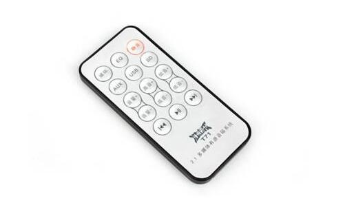
The picture above is a very common car MP3 remote control, which is relatively small and easy to use. The following are the principles of infrared emission and acceptance:
At this point, the reader may have doubts, so the pulse rules of different modulation and demodulation methods are different. Yes, it is.
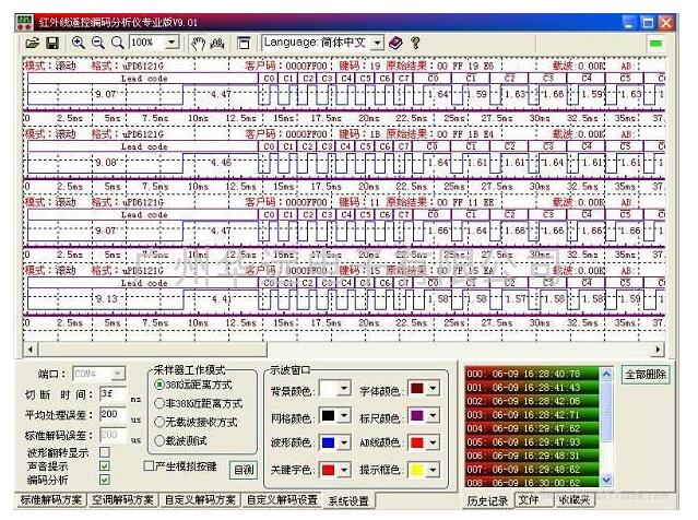
There are many special chips for remote control transmitters. They can be divided into two categories according to the encoding format. Here we explain them in a class that is more widely used and easier to decode. Now we use the uPD6121G of Japan NEC as a transmission circuit to illustrate the coding principle (general family). This type of encoding is used for DVD, VCD, and audio. When the transmitter button is pressed, the remote control code is sent, and the pressed key has different remote control codes. This remote control code has the following characteristics:
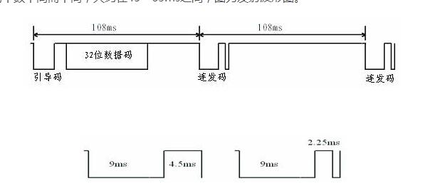
Using a pulse width modulated serial code, a combination of a pulse width of 0.565 ms, an interval of 0.56 ms, and a period of 1.125 ms represents a binary "0"; a combination of a pulse width of 0.565 ms, an interval of 1.685 ms, and a period of 2.25 ms. Represents a binary "1" whose waveform is as shown.
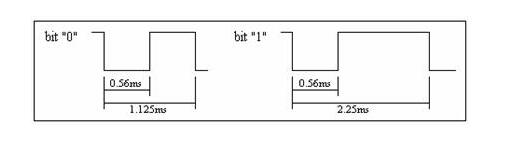
As can be seen, the low level of 0 and 1 front ends are both 0.56ms, then the high level duration is different, 0 is 0.56ms, 1 is 1.685ms, find the difference, there is recognition when programming Based on!
The 32-bit binary code composed of the above “0†and “1†is secondarily modulated by the carrier frequency of 38 kHz to improve the transmission efficiency and achieve the purpose of reducing the power consumption of the power supply. Then, infrared rays are generated by the infrared emitting diode to emit into the space as shown in the figure.
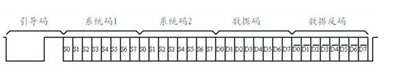
The remote control code generated by the UPD6121G is a continuous 32-bit binary code group, in which the first 16 bits are user identification codes, which can distinguish different electrical devices and prevent different types of remote control codes from interfering with each other. The chip's user ID is fixed to hexadecimal 01H; the last 16 bits are 8-bit opcode (function code) and its inverse. The UPD6121G has a maximum of 128 different combinations of codes.
Please see the picture below, from the network:
When a key is pressed for more than 36ms, the oscillator activates the chip and will transmit a set of 108ms coded pulses. The 108ms transmit code consists of a boot code (9ms), a result code (4.5ms), and a lower 8-bit address code (9ms). ~18ms), high 8-bit address code (9ms~18ms), 8-bit data code (9ms~18ms) and the inverse of these 8-bit data (9ms~18ms). If the key is not released after more than 108ms, the next transmitted code (continuous code) will consist of only the start code (9ms) and the end code (2.25ms). (Actually, the movement of the human hand is very slow, even if you press the button quickly, it may still be more than 108ms for the chip, so how to deal with the burst code is very important)
After the button is pressed, the remote controller periodically sends out the same 32-bit binary code with a period of about 108 ms. The duration of a set of codes themselves varies with the number of binary "0"s and "1"s it contains, approximately between 45 and 63 ms. The graph is a transmitted waveform.
The infrared remote control device includes two parts: infrared emission (ie, remote control) and infrared reception. Since almost all objects are constantly emitting infrared rays, how can we ensure that the control signals transmitted by the designated remote control can be accurately received by the receiving device without interference from other signals, which requires Control in four links.
1. The infrared sensor is matched with the infrared emission sensor and the infrared receiving sensor, which constitutes an infrared remote control system.
The infrared emission sensor for remote control, that is, the infrared light emitting diode, is made of a semiconductor material such as gallium arsenide or gallium arsenide, and the former has lower luminous efficiency than the latter. The peak wavelength is the wavelength of the light corresponding to the maximum infrared intensity emitted by the infrared light emitting diode. The peak wavelength of the infrared light emitting diode is usually 0.88 μm~O.951 Am. The infrared receiving sensor for remote control has two kinds of photodiode and phototransistor. The response wavelength (also called peak wavelength) reflects the spectral response characteristics of the photodiode and phototransistor. It can be seen that to improve the efficiency of collection, it is very important that the peak wavelength of the infrared light-emitting diode used in the remote control system and the response wavelength of the infrared receiving sensor must be the same or similar.
2. Signal Modulation and Demodulation The infrared remote control signal is a series of binary pulse codes. In order to protect it from other infrared signals during wireless transmission, it is usually modulated on a specific carrier frequency and then transmitted through an infrared light-emitting diode. The infrared receiving device filters out other clutter only. The signal of the particular frequency is received and restored to a binary pulse code, ie demodulated. The figure below is a schematic diagram of infrared transmission and reception. The state in which no signal is emitted in Fig. 1 is called an empty number or a zero state, and a state in which a signal is pulsed at a certain frequency is referred to as a mark or a state. In the infrared remote control system of consumer electronics, the carrier frequency of the infrared signal is usually 30 kHz--OkHz, and the standard frequencies are 30 kHz, 33 kHz, 36 kHz, 36.7 kHz, 38 kHz, 40 kHz, and 56 kHz. Other frequencies in this range can also be identified.
3, encoding and decoding
Since the infrared remote control signal is a series of binary pulse codes, then what combination of space number and mark number is used to represent the "0" and "1" of the binary number, that is, the coding mode used for signal transmission is also an infrared remote control signal. The sender and receiver need to be agreed in advance. Generally, there are three encoding methods used in infrared remote control systems:
1) FSK (Frequency Shift Keying) mode
The frequency shift keying method uses two different pulse frequencies to represent the "0" and "1" of the binary number respectively. The following figure is a schematic diagram of encoding "0" and "1" by the frequency shift keying method.
2) PPM (Pulse Position Coding) mode
In the pulse position mode, the time occupied by each binary number is the same, except that the position of the mark pulse is different. The empty number is in front and the trailing number is "1", the leading number is in front and the empty number is followed by "0". The figure below is a schematic diagram of encoding "0" and "1" using pulse position coding.
3) PWM (Pulse Width Coding) mode
The pulse width coding method distinguishes the "0" and "1" of the binary number according to the width of the mark pulse.
The width of the mark pulse is "1", the narrow pulse of the mark is "0", and the number of bits between each bit is used.
Since the infrared remote control does not have the ability to pass through obstacles to control the controlled object like a radio remote control, it is not necessary to design each household's infrared remote control like a radio remote control (transmitter and receiver). There must be different remote control frequencies or codes (otherwise, the wall will control or interfere with the neighbor's household appliances), so the infrared remote control of the same product can have the same remote frequency or code without the remote control signal "serial door" Case. This provides great convenience for mass production and popularization of infrared remote control in household appliances. Since infrared light is invisible light, it has little impact on the environment, and then the infrared light fluctuation wavelength is much smaller than the wavelength of the radio wave, so the infrared remote control does not affect other household appliances, and does not affect adjacent radio equipment.
An electric slip ring is a rotary electrical connector. It allows uninterrupted power or signal transfer between two stationary points. It is also known as an electric Rotary Joint, power swivel, or electrical rotary joint. Electric slip rings are usually composed of a metal ring with several brush contacts on the inner circumference. And there are one or more pairs of contacts for power or signals on the outer circumference. The metal ring can be rigid or flexible, depending on the application.
An electric slip ring is an electromechanical device that allows the transmission of electrical power and signals from a stationary to a rotating structure. It consists of an electrically conductive rotating disc or ring, with a number of electrical contacts (or "slots") on its surface. The contacts are connected to external circuits, enabling the passage of power and/or data from the stationary to the rotating structure. Slip rings are also used in generators, where they allow the passage of current from the rotor to the stator.
A flat disc electrical slip ring is one kind of electric slip ring, it has many advantages: simple construction, small size, low cost, easy installation, and maintenance. It is widely used in various fields such as machine tools, textile machinery, printing machinery, packaging machinery, medical equipment, and aerospace equipment.
A 360-degree rotating Conductive Slip Ring is also called a hollow shaft slip ring or hollow conduct. It has an opening in the center that allows a shaft to pass through, making it ideal for rotating applications. Slip rings are often used in medical equipment, robotics, and manufacturing assemblies where rotation is required. This type of slip ring can handle large currents and voltages while providing a continuous electrical connection.
Electric Slip Ring,Slip Rings In Generator,Flat Disc Electrical Slip Ring,Slip Ring Electric Motor
Dongguan Oubaibo Technology Co., Ltd. , https://www.sliprob.com