
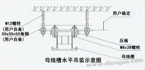
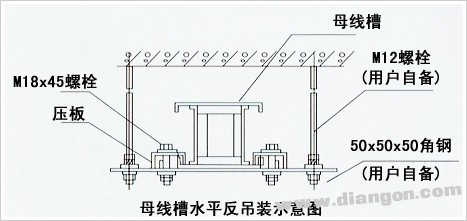
1. The busway channel is installed horizontally. The distance between the two brackets is 5002500mm, and the vertical installation spacing is 6003600mm.
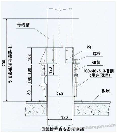
2. When installing vertically, the mounting bracket should be drilled with the side plate of the channel and fastened with M6-M8 bolts.
3. For the installation and construction process, the construction plan from the feeding system to the branch line should be preferred;
4. Basic sequence of closed busway installation:
Select the wiring direction → fixed bracket → four bolts are fastened between the slots → the busbar joint plate and the insulating pad are added between the phases → the single-head bolt penetrates the insulating sleeve → the bolt penetrates into the busbar to pre-dispose the hole → the two ends are fastened → add Half mounted upper and lower cover → Secure the channel to the bracket.
5, the installation of the channel bus, the beginning, the middle, the terminal and the channel housing should be reliably connected to the grounding grid of the electrical equipment. The channel outer shell of the insulating material shall be connected with a flat copper strip or a yellow-green phase cable on the grounding bolt between the two channels to ensure that the entire passage is connected to become a grounding system.
6. After the installation project, apply the shaking table before the power transmission to test the channel busbar phase insulation and grounding insulation resistance: 1 low voltage busbar channel is not less than 20MΩ; 2 for 6~10KV high voltage busbar channel insulation resistance is not less than 1200MΩ. The 35KV insulation resistance is not less than 3000MΩ.
7. Before the power transmission, the 6~35KV bus channel should be tested for 50HZ power frequency withstand voltage and DC leakage test, and it can be put into operation after passing the test;
8. In the bus passage that is put into operation, the busbar joint bolts should be tightened in three months to check the contact condition of the busbar joints;
9. The bus route to be commissioned shall be inspected at least once a year for the following items:
(1) Fasten the fixing bolts, especially the busbar joints, and observe whether the joints have a burning phenomenon caused by poor contact or overcurrent, and handle them;
(2) Shaking the table to test the degree of insulation and checking whether the insulating material is aging;
(3) the connection between the busway and the grounding grid;
(4) It is clear that the inside and outside absorb the attached dust and condensate;
10. Notes:
(1) Before the maintenance of the busway, the power distribution cabinet must be powered off first, and the <man-operated, strictly closed> Peugeot card should be hanged.
(2) Before the start of maintenance work, it should be checked and discharged, and the grounding rod should be used to short-circuit the phase and reliably ground before operation;
11. Custody of the busway:
It should be placed in a dry and ventilated place indoors to prevent moisture, rain and snow from entering, and prevent dust or foreign matter from entering the passage.
The products can provide various specifications of rectifier bridge devices according to customer requirements. The electrical properties, appearance, reliability, safety indicators and environmental protection indicators of the products all meet the relevant standards.
Planar Die Construction Sealed Glass Case Ideally Suited for Automated Insertion - 75V Nominal Zener Voltages
Case: MiniMELF, Glass Terminals: Solderable per MIL-STD-202, Method 208 Polarity: Cathode Band Approx. Weight: 0.05 grams= 25°C unless otherwise specified Symbol Pd VF RqJA Tj, TSTG Value to +175 Unit mW V K/W °C
Characteristic Forward Voltage = 200mA Thermal Resistance, Junction to Ambient Air (Note 2) Operating and Storage Temperature Range Notes:
1. Tested with Pulses, 20ms. 2. Valid provided that Electrodes are kept at Ambient Temperature.
1. Tested with pulses = 20 ms. 2. Valid provided that electrodes are kept at ambient temperature.
VZ, ZENER VOLTAGE (V) Fig. 1, Zener Current vs Zener Voltage
25 20 VZ, ZENER VOLTAGE (V) Fig. 8, Zener Current vs Zener Voltage
TA, AMBIENT TEMPERATURE (°C) Fig. 3, Power Dissipation vs Ambient Temperature
15 20 VZ, ZENER VOLTAGE (V) Fig. 4, Differential Zener Impedance
VZ, ZENER VOLTAGE (V) Fig. 5, Junction Capacitance vs Zener Voltage
MINI MELF,Smd mini melf,zener mini melf,mini melf package,mini melf resistor,mini melf diode,mini melf resistor datasheet
Changzhou Changyuan Electronic Co., Ltd. , https://www.cydiode.com