
Controller Area Network (CAN) is a serial communication protocol bus for real-time applications. It can transmit signals using twisted pairs. It is one of the most widely used fieldbuses in the world. Developed by Robert Bosch of Germany, the CAN protocol is used to communicate between various components in a car, replacing expensive and cumbersome distribution harnesses. The robustness of the protocol extends its use to other automation and industrial applications. Features of the CAN protocol include integrity of serial data communication, real-time support, transfer rates up to 1Mb/s, simultaneous 11-bit addressing, and error detection.
The CAN bus is a multi-master serial communication bus. The basic design specification requires high bit rate, high immunity to electronic interference, and the ability to detect any errors generated. CAN bus can be applied to automotive electric control systems, elevator control systems, safety monitoring systems, medical instruments, textile machinery, ship transportation and other fields.
CAN bus features
1. It has the advantages of strong real-time performance, long transmission distance, strong anti-electromagnetic interference capability and low cost;
2. It adopts two-wire serial communication mode, which has strong error detection capability and can work in high noise interference environment;
3. With priority and arbitration function, multiple control modules are connected to CAN-bus through CAN controller to form a multi-host local network;
4. The message can be received or blocked according to the ID of the message;
5. Reliable error handling and error detection mechanism;
6. After the sent information is destroyed, it can be automatically resent;
7. The node has the function of automatically exiting the bus in case of serious error;
8. The message does not contain the source address or the destination address, and only the identifier is used to indicate the function information and the priority information.
How the CAN bus works
The CAN bus uses serial data transmission, which can run on a 40m twisted pair at a rate of 1Mb/s, or it can be connected using fiber optic cable, and the bus protocol supports multi-master controllers on this bus. CAN and I2C bus are very similar in many details, but there are some obvious differences.
When a node (station) on the CAN bus transmits data, it broadcasts it to all nodes in the network in the form of messages. For each node, whether the data is sent to itself or not, it is received. The 11-character character at the beginning of each group of messages is an identifier that defines the priority of the message. This message format is called a content-oriented addressing scheme. In the same system the identifier is unique and it is not possible for two stations to send messages with the same identifier. This configuration is important when several stations compete for bus reads at the same time.
When a station wants to send data to other stations, the CPU of the station sends the data to be sent and its own identifier to the CAN chip of the station, and is in the ready state; when it receives the bus assignment, it changes to send the message. status. The CAN chip sends the data according to the protocol and is organized into a certain message format. At this time, other stations on the network are in the receiving state. Each station in the receiving state detects the received message and determines whether the message is sent to itself to determine whether to receive it.
Since the CAN bus is a content-oriented addressing scheme, it is easy to build a high-level control system and configure it flexibly. We can easily add some new stations to the CAN bus without having to modify them in hardware or software. When the new station provided is a pure data receiving device, the data transfer protocol does not require a separate portion to have a physical destination address. It allows the distribution process to be synchronized, ie when the controller on the bus needs to measure data, it can be obtained online, without having to have its own separate sensor for each controller.
CAN bus application
The advantages of the CAN bus in networking and communication functions and its high cost performance have determined that it has broad application prospects and development potential in many fields. Some of these applications have in common: CAN is actually the role of a computer LAN that acts as a bus topology in the field. No matter what the occasion, it bears the real-time communication between any node, but it has the advantages of simple structure, high speed, anti-interference, reliability and low price. The CAN bus was originally designed for automotive electronic control systems. The use of CAN in cars currently produced in Europe is very common. Not only that, but the technology has been extended to trains, ships and other vehicles.
1. The application of CAN bus in automobile manufacturing can reduce the body wiring and further save the cost. Due to the bus technology, only two signal lines are needed for signal transmission between modules. The wiring is localized, and all the lines that cross the body except the bus are no longer needed, saving wiring costs. The CAN bus system data is stable and reliable, and the CAN bus has the characteristics of small inter-line interference and strong anti-interference ability. The CAN bus is specially tailored for the car, taking into account the harsh working environment of the car, such as the powerful anti-charge voltage generated when the ignition coil is ignited, the surge current generated when the eddy current buffer is cut off, and the car engine compartment is about 100 °C. high temperature. 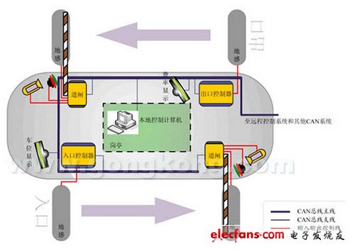
As safety performance becomes more and more important, airbags will gradually increase. Previously, one was installed in front of the driver. In the future, airbags will be installed on the side and rear seats. These airbags will sense the collision signal through the sensor and transmit the sensor signal through the CAN bus. A central processor controls the startup pop-up action of each airbag. At the same time, advanced anti-theft design is also based on CAN bus network technology. Firstly, the verification information of the legality of the key is confirmed to be transmitted through the CAN network, and the encryption algorithm is improved. The verification information is richer than the previous anti-theft system. Secondly, the car key, the anti-theft controller and the engine controller store each other's information. Moreover, the random code in the check code is noisy and can not be deciphered, thereby improving the security of the anti-theft system. The realization of these functions is completed by the CAN bus, and the CAN bus becomes the "Dinghai Shenzhen" for intelligent control of automobiles.
In the design of modern cars, CAN has become a must-have device. Mercedes-Benz, BMW, Volkswagen, Volvo, Renault and other vehicles have adopted CAN as a means of networking controllers. According to reports, China's first CAN network system hybrid car has been successfully installed in Chery and has undergone preliminary trial operation. CAN bus technology was also introduced in Shanghai Volkswagen's Passat and POLO cars. But in general, the current application of CAN bus technology in China's automotive industry is still in the test and initial stage, and most of the cars have not adopted the car bus design. It is imperative to carry out the “deep-in-depth†of the network bus in technology, design and application in China.
2. Application in large-scale instruments and equipment Large-scale instruments and equipment are complex systems that refer to certain steps for the collection, processing, control, and output of various information. In the past, the electronic systems of such instruments and equipment often occupied a considerable part in terms of structure and cost, and the reliability was not high. After adopting the CAN bus technology, there has been a significant improvement in this respect. 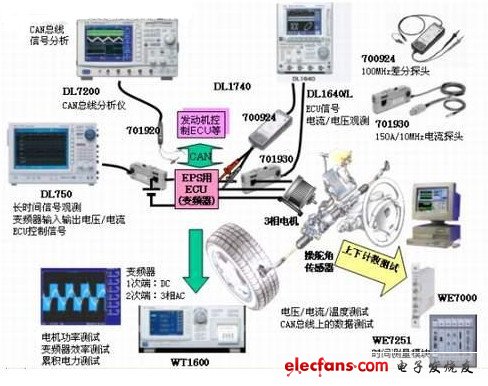
Taking medical equipment as an example, the pathological distributed monitoring system consists of a centrally controlled central monitoring unit and a field acquisition unit. The on-site collection unit collects data and images in real time from the diagnostic and measuring instruments in each hospital, and simultaneously completes data statistics and storage. The central monitoring unit can obtain data from the on-site collection unit periodically or irregularly and complete image monitoring, data statistics and reports. , printing and database management. The central monitoring unit and the field acquisition unit are connected together via a CAN bus. In this network, the central monitoring unit is in the master position, and the field acquisition unit can respond to commands from the central monitoring unit at any time. The field acquisition unit consists of a single-chip 8C552 and acquisition, storage, display, remote control and communication modules. Each field acquisition unit can be connected to 10 measuring instruments.
The Can bus is designed for the field of measurement and control, so the amount of messages transmitted at one time is very small. The maximum amount of data that can be carried in one packet is 8 bytes. The transmission of such small data can make low-priority transactions on the one hand. Transmission, on the other hand, is also very suitable for measurement and control needs. Aiming at the many advantages of the CAN bus technology, it is very suitable for the mutual communication between the modularization of large instrument systems, and the large-scale instrument system is constructed by modular networking.
3. Application in industrial control With the development of computer technology, communication technology and control technology, the traditional industrial control field is undergoing an unprecedented transformation, and the network of industrial control expands the development space in the field of industrial control. , bringing new development opportunities. In a wide range of industrial fields, the CAN bus can be used as a field-level communication bus, and it has high reliability and cost-effectiveness compared to other buses. This will be a major direction for CAN technology development applications. 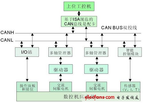
For example, the axis control system ACS-E developed by a Swiss company has a CAN interface. The system can be used as a slave in industrial control networks to control machine tools, robots, etc. On the one hand, the upper computer communicates on the CAN bus, and on the other hand, the digital servo motor can be controlled via the CAN bus. Up to 6 digital servo motors can be connected via the CAN bus.
At present, the application of CAN bus technology in construction machinery is more and more common. Some well-known engineering machinery companies in the world such as CAT, Volvo, Lieb, Haier, etc. widely use CAN bus technology in their products, which greatly improves the reliability, detectability and maintainability of the whole machine, and improves the system. Intelligent level. In China, the CAN bus control system has also been widely used in the control system of engineering vehicles, and is gradually being promoted and applied in the construction machinery industry.
4. Application of intelligent home and living community management The intelligentization of the community is a comprehensive system engineering, which should be considered from the aspects of its functions, performance, cost, expansion capability and application of modern related technologies. Based on such requirements, the home intelligent management system designed by CAN technology is more suitable for multi-table remote transmission, anti-theft, fire prevention, flammable gas leakage, emergency rescue, home appliance control and so on. 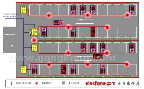
The CAN bus is part of the cell management system. It collects some data and signals from the home and sends them to the community management center. The nodes on the CAN bus are the home controller of each household, the three-meter copying system and the alarm of the community. The monitoring system, each household's home control system can send alarm signals through the bus, periodically send three-table data to the automatic meter reading system, and receive notification information of the cell management system, such as arrears notification, fire alarm, and the like.
The system makes full use of the characteristics and advantages of CAN technology to form a residential residential intelligent detection system, which integrates functions such as multi-table copying, anti-theft alarm, water and electricity control, emergency help, gas leak alarm, fire alarm and power supply monitoring subsystem. Provide remote communication services.
5. The automation of the underlying equipment in the application manufacturing workshop of the robot network interconnection is still the main field of new technology research and new technology application engineering and product development in China in recent years. Its market demand is increasing and more active, and competition is becoming increasingly fierce. . Along with the industrialization of industrial robots, most of the current applications of robotic systems require the use of robotic production methods, which requires multiple robots to be interconnected through the network. As a result, in the actual production process, the scheduling and maintenance of such networked multi-robot systems has become particularly important. The interconnection of electrical equipment at the bottom of the manufacturing workshop is the focus of technological development in recent years. The electrical device includes: an underlying device such as a motion controller, a microprocessor-based sensor, and a dedicated device controller; and a non-bottom layer of a shop-level management machine, a monitoring machine, or a production unit controller on a network formed by these devices; Device. The robot controller is considered as a motion controller in combination with actual conditions and requirements. 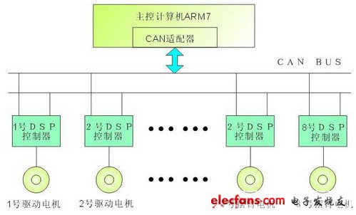
By fully applying CAN bus technology to existing controllers, a high-performance multi-robot production line system can be developed. Utilizing the existing control technology, combined with CAN technology and communication technology, through the hardware improvement and software development of the existing robot controller, and correspondingly developing the host computer monitoring software, the network interconnection of multiple robots is realized. Finally, the robot network production line integration system based on CAN network is realized. There are many advantages to this, such as implementing a single cable to connect all devices, saving installation and maintenance overhead; improving real-time performance, sharing information; improving detection, diagnosis, and control performance of multi-controller systems; scheduling tasks and operations through offline tasks Techniques such as downloading and error monitoring completely remove some people from the scene where the robot works.
CAN bus data communication has outstanding reliability, real-time and flexibility. Due to its good performance and unique design, the CAN bus has received more and more attention, and it is the most widely used in the automotive field. Most famous automobile manufacturers in the world use the CAN bus to realize data communication between the internal control system of the vehicle and each detection and execution mechanism. At the same time, due to the characteristics of the CAN bus itself, its application range is no longer limited to the automotive industry, but to the automatic control, aerospace, marine, process industry, machinery industry, textile machinery, agricultural machinery, robots, CNC machine tools, medical equipment. And the development of sensors and other fields. CAN has become an international standard and has been recognized as one of several of the most promising fieldbuses.
Half-cell Polycrystalline Solar Panel
Half-Cell Polycrystalline Solar Panel,340W Half Cell Solar Panel,High Efficiency Polycrystalline Solar Cell Panel,Half-Cell Poly Solar Panel
Jiangsu Stark New Energy Co.,Ltd , https://www.stark-newenergy.com