
This circuit can be used for single-chip systems such as the MCS-51 series. The electrical principle is shown in the drawing.
In the figure, a four-input "2-NAND" Schmitt trigger 74HC1320 has its door c, door d, door b and C3, C4, R4, R5, D3, D2, etc.
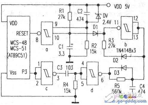
The circuit, unlike the "watchdog" circuit that people are familiar with, has no oscillating circuit. In the figure, gates c and C3 are isolated, and the input of gate c can be connected to an I/O pin that is frequently changed in the main loop of the system program (because it is a standard CMOS high-impedance input, it does not affect the I/O. Pin function), you can also set an I/O pin for it, such as P3.7 port, as long as you add an instruction to reverse the port (such as CPLP3.7) in the main loop program - - A small loop of the port outputs a high level, and then a loop output low level ... In this way, the output of the door c output 3 feet constantly changes, the output of the door d of the 6 feet also changes. When pin 6 is high, charge C4 through R5. When pin 6 is low, C4 is quickly discharged through diode D3. Therefore, as long as the main loop of the system program runs normally, the I/O port output continues. Change, that is, the 6 feet of the door d are constantly changing, C4 is not charged and is always at a low level, and is applied to the door b, so that the 10th foot of the door b outputs a high level, so that the door is blocked due to D1 and D2, b does not affect the entire circuit, the entire system remains in normal operation.
If the system is interrupted and the program crashes or the program runs away, the main loop cannot operate normally, then the I/O port (P3.7) no longer changes. At this time, the input of the gate c remains at the high level or the low level. Due to the isolation of the capacitor C3, the input terminals 4 and 5 of the gate d have the pull-down of the resistor R4, and the output of the 6-pin is always at a high level, and the C4 is charged through the R5. After about 500 ms, the output of the gate b (11) is low. Level. On the one hand, C1 is quickly discharged by D1, so that the 10th pin of the gate a is low level, and the 8th pin of the gate a outputs a high level, causing the CPU to reset. On the other hand, C4 is discharged through D2 and R3. When C4 is discharged to the VL threshold level, the gate b is flipped, and the 11th pin outputs a high level, which blocks D1 and D2, so that the capacitors C1 and C4 start with R1 and R5 respectively. Charging, since the charge and discharge time constants of R1 and C1 are only a fraction of R5 and C4, the gate a is flipped first, and the 8th pin outputs a low level, and the CPU resumes normal operation after resetting. Once the main loop is running normally, the input of the gate c changes continuously, the output of the gate b also changes continuously, and the C4 is not charged. In the figure, the gate a and the resistors R1 and R2, the capacitors C1 and C2, and the Zener diode DW constitutes the voltage monitoring circuit. R1 and C1 on the gate a10 are mainly used for “power-on automatic resetâ€. That is, in the initial stage of system power-on, the gate a10 is at a low level, and its 8-pin output is reset. Pulse, CPU reset. C2, R2, and DW on the 9th pin of the door a play the role of "power failure protection". At the moment of power-on, due to the existence of C2, the 9-pin is at a high level. When the power supply voltage is stable, the potential of the 9-pin is clamped at VDD-2.4=5-2.4 due to the presence of the 2.4V Zener diode DW. =2.6V, according to the characteristics of Schmitt trigger, 9 feet are still "held high", will not affect the original state of the door a. When the system power supply is powered down or under voltage, if VDD drops to 4V, the potential of the 9 pin is VDD - 2.4 = 4-2.4 = 1.6V, which is lower than the VL threshold voltage. At this time, the door a is flipped, and the 8-pin output level is high, so that the CPU is in the reset state, which avoids the misoperation caused by the system during the power-down and under-voltage process, until the power supply returns to normal, the reset protection is cancelled, and the CPU starts. normal operation.
ZGAR Vape Pods 1.0
ZGAR electronic cigarette uses high-tech R&D, food grade disposable pods and high-quality raw material. A new design of gradient our disposable vape is impressive.We equip with breathing lights in the vape pen and pods.
Our team has very high requirements for product quality, taste allocation and packaging design. Designers only use Hong Kong designers, e-cigarette liquid only imports from the United States, materials are food grade, and assembly factory wants medical grade without ground workshop.
We offer best price, high quality Pod System Vape,Pods Systems Touch Screen,Empty Pod System, Pod Vape System,Disposable Pod device,Vape Pods to all over the world.


Pods,Vape Pods,Pod Systems,Atomizer, E-cigarette, Empty Pod Vape Manufacturer and Supplier in China
ZGAR INTERNATIONAL(HK)CO., LIMITED , https://www.zgarette.com