
Abstract: A body central controller BCM is designed for a certain model, which realizes functions such as door lock control, lighting control, wiper control, window control, LIN communication, and RKE communication. BCM adopts Freescale's S12 series 16-bit microprocessor MC9S12XS128 to design, and realizes IO expansion through multi-way switch detection chip MC33993, which solves the switching signal acquisition under the limited condition of multi-channel switch and processor IO pin, and the switch signal detection program design The general structure is used to unify the state monitoring and change capture functions of each switch signal, improving code efficiency and operational stability. At the same time, the hardware structure of BCM is also described, and the software flow is designed according to the working mode of BCM.
Key words: body controller; MC9S12XS128; switching signal detection; MC33993; load control
Freescale's S12 series of 16-bit MCUs are widely used in body control systems for body controller BCMs, door lock modules, RKE receivers, smart actuators, lighting modules and other body ECUs. In the BCM developed by a whole vehicle factory, MC9S12XS128 is used as the central processor to realize most functions of body control, including door lock control, lighting control, wiper control, window control and anti-theft alarm, and also realize CAN/ The LIN gateway function, which receives the vehicle speed and collision signals through the CAN bus, enables safe driving and emergency operation, receives signals from the rain sensor through the LIN bus, and controls the fast, slow or intermittent operation of the wiper. The following is an introduction to the application of the MC9S12XS128 in BCM from the key technical aspects of hardware design and software design.
1 hardware design
1.1 Introduction to MC9S12XS128 MC9S12XS128 is a high-performance 16-bit single-chip microcomputer for the automotive electronics market. It features fast speed, powerful functions, low cost and low power consumption. Its chip resources and features are as follows:
1) Bus speeds up to 40 MHz;
2) 128 KB program Flash and 8 KB DataFlash for program and data storage, all with error correction code (ECC);
3) Configurable 8-bit, 10-bit or 12-bit ADC with 3μs conversion time;
4) The embedded MSCAN module is used for CAN node application, and the enhanced SCI module and SPI module supporting LIN protocol are embedded;
5) 4-channel 16-bit counter;
6) Excellent low-power characteristics, with interrupt wake-up function 10, to achieve the function of wake-up sleep system;
7) 8-channel PWM for easy motor control.
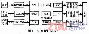
1.2 System Structure The BCM hardware system structure based on S12XS128 is shown in Figure 1. As can be seen from the figure, the BCM hardware circuit includes switch signal detection, CAN/LIN communication, load control and monitoring. The switch signal detection is realized by the multi-way switch detection chip MC33993. The LIN communication is realized by the UART module and the LIN bus physical layer transceiver TJA1021. The CAN communication is realized by the CAN module and the CAN bus physical layer transceiver TJA1055, and the load control is passed through the intelligent power. In the device implementation, in addition to realizing the power drive to the load, the intelligent power device can also provide a mirrored working current, so that the load can be monitored by the mirrored working current sampling ADC conversion.
This article refers to the address: http://
1.3 Switching Signal Detection In the design and implementation of BCM, the control of the control load triggered by the switch state and its state change is the most common and most important control method. Due to the large number of switching signals, the control load of BCM is mostly used. The way of 10 is controlled, so how to complete the monitoring of multiple switch states becomes a big challenge in the case of the limited IO pin of XS128. At the same time, for battery-powered automotive electronics applications, BCM itself has low power consumption requirements. When low power consumption conditions are met, the low power mode is entered, the system shuts down unnecessary modules, reduces power consumption; when several specific switches When the state changes, the system needs to start the relevant module and enter the normal working mode, so that not only the switching state acquisition and the state change capture in the normal working mode but also the wake-up function in the low power mode are needed.
Some of the switching signals are collected in a discrete manner, and the rest are implemented using the Freescale programmable multiplexer detection interface chip MC33993. The hardware circuit is shown in Figure 2.
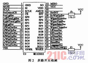
The MC33993 communicates with the processor via the SPI to detect 22 digital input signals and can set which switching channels can trigger an interrupt. First, the XS128 sends a control command word to the MC33993 through the SPI, performs initial setting, sets the working mode of the MC33993, and enables the trigger interrupt function of the switch channel that wakes up. In the normal working mode, the XS128 reads the switching state of the MC33993 through the SPI interface cycle. When the state of the switching channel that can trigger the interrupt changes in the low power mode, the XS128 can be woken up and enter the normal working mode.
2 software design
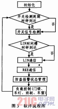
2.1 Software Process Design The software design of BCM adopts the software structure of initialization + loop body. The software flow chart is shown in Figure 3. First, the global variables and the peripherals used (including IO, ADC, SPI, PWM, TIME-R, SCI) are initialized, and then the switch signal detection, LIN communication, RKE communication, and load control are sequentially performed in the loop body. For the load control logic, the switching signal, the LIN signal and the RKE signal are the input signals that trigger their control operations, and since several switching signals need to be filled into the LIN frame, the load control is placed at the end of the loop body, each The software module sequence is shown in Figure 3.
2.2 Switch signal detection software design In the switch control logic of BCM, the state of the switch signal and its change often serve as the background condition and excitation signal of a certain control logic. Therefore, in the design of the program, it is necessary to determine the signal of a single physical switch. Current state and state transitions (including switch closure to open and switch open to closed changes). Because the BCM needs to collect more switching signals, in order to simplify the program and clear the logic, define a structure to unify the switching signals, use the bit variable characteristics of the structure to save the variable space, and use the uniformity of the structure to save the switching signal. Detect the code space of the function. The design structure is as follows: 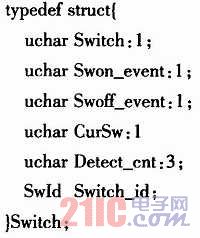
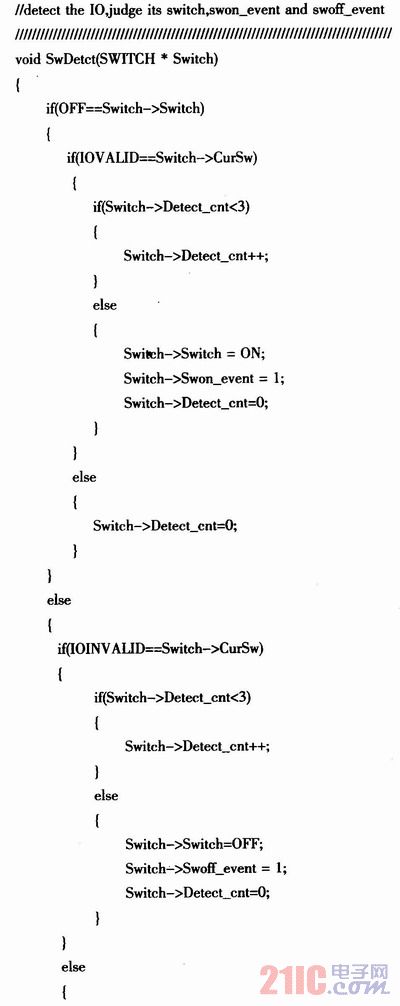
In the above structure, Switch represents the current state of the switching signal, and Swon_event and Swoff_event represent the change of the switch from open to closed and from closed to open, respectively, and CurSw and Detect_cnt are used for software signal debounce of switching signal acquisition. Design a 10 ms timer, periodically read the current state of the switch, and confirm it 3 times to determine Switch, Swon_event, and Swoff_event. The code is implemented as follows: 

3 Conclusion The MC9S12XS128 design is used to realize a body central controller BCM. The hardware design of BCM is described from the aspects of processor characteristics, hardware structure, multi-switch expansion and switching signal detection. From software flow design, switch signal status monitoring and The software design of BCM is described in the software implementation of change capture. The BCM has been loaded and tested, stable in operation and reliable in function. It has entered the stage of small batch pre-production and has high practical value.
High-Speed 3D Filament Extrusion Line,Precision 3D Filament Extrusion Line,Customizable 3D Filament Extrusion Line,Advanced 3D Filament Extrusion Line Technology
Zhejiang IET Intelligent Equipment Manufacturing Co.,Ltd , https://www.ietmachinery.com