
Abstract: Visual navigation, as an emerging technology, is favored by many researchers. An autonomous navigation car with field programmable gate array (FPGA) as the control core is designed. A novel adaptive path recognition algorithm is used to realize the path identification and extraction, and the auto-independence of the car is completed by combining the circular route planning and control strategy. Navigation control. The adaptive path recognition algorithm enables the navigation car to adapt to a variety of lighting and road conditions. The test results show that the car can achieve better navigation effect in the laboratory and open track and track environment under different lighting conditions. In the navigation test on the track and field runway, the maximum running speed of the car reaches 3.5m/s.
At present, most of the control processing cores used in the research of visual navigation vehicles are single-chip microcomputers or digital signal processing (DSP) chips [1-2]. The advantages of this type of processing core are low cost and ease of use. However, due to the limited image processing speed of the single chip and DSP, the video image needs to be downsampled to adapt to the speed of video capture, thus affecting the effect of image processing and recognition. The use of field programmable gate array (FPGA) chips can greatly improve the speed of image processing and recognition, and overcome the above shortcomings. FPGA is a new type of information processing system, which is a computing platform between software and hardware. It can be programmed in the same way as software, or it can directly control the gate circuit to perform operations like hardware. This feature makes it easier to implement parallel computing, improve image processing speed and ensure real-time image processing. Therefore, FPGA is very suitable for the control center of vision control system [3].
On the basis of quickly and accurately processing and analyzing the image, the control processing center can obtain the relative position of the trolley and the path in real time, and according to the route planning and motion control of the trolley, realize the autonomous navigation of the trolley. There has been a lot of research on route planning [4-15]. Liu [9], Fu [10], etc., based on the distance between the current position and the target position of the trolley and the deviation of the corner as a parameter to design a fuzzy control table to control the car; Hsueh et al [11] calculated the position and angle deviation Improve and design a proportional-integral-derivative (PID) controller to realize autonomous navigation of the car; Liu Haitao et al [12] proposed a fuzzy control method based on pattern matching; Li Jin et al [13] proposed a straight line fitting to extract path information. , combined with PID control to complete the car autonomous driving method. Ren Yongxin et al. [14] proposed to divide the control into two parts: the fuzzy control and the small turning path of the large corner part adopt precise control method. In the case of a small turn, a planned circular path is designed. According to the radius of curvature of the circular path, the control amount of the two driving wheels of the trolley is controlled by a certain conversion relationship, and the steering control of the trolley is realized. In this paper, OV7620 is used as the image sensor, and FPGA is used as the core controller. The car navigation control system is realized by image acquisition, path recognition and look-up table technology.
1 hardware structureThe image acquisition of the autonomous navigation car adopts the C3188 camera module equipped with the OV7620 image sensor. The FPGA control board adopts the Spartan3E development board of Xilinx Company, and the car is the Henglong 3851-2 remote control four-wheel drive off-road model car.
The car acquires image information through the image sensor chip OV7620. The FPGA uses the three clock signals provided by the image sensor chip as the synchronization signal to complete the image acquisition. The digital interface of the FPGA control board is directly connected to the 8-bit data line of the camera and the corresponding control signal to achieve fast acquisition of the video signal. The image rate is 30 frames/s.
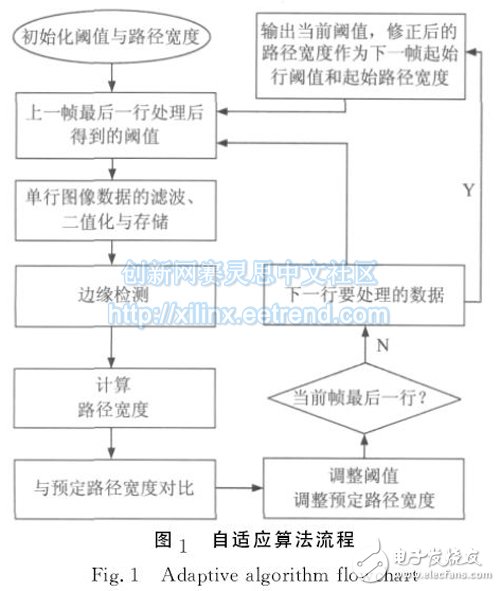
2 path identification and route planning 2.1 Path Recognition Path Recognition First, the image is binarized. Although there have been many studies on image binarization algorithms, the most simple fixed threshold method is widely used because of the high computational speed required by visual navigation. However, the fixed threshold binarization method is very sensitive to the ambient lighting conditions and background noise, so that the corresponding path recognition effect requires high environmental conditions and is very unstable. Therefore, we propose an adaptive path recognition method that combines the two separate steps of image binarization, path position and width determination, starting from a set of preset path widths and binarization thresholds. The image is processed line by line, and the preset values ​​of the width and the threshold are adjusted according to the width of the previous line and the threshold calculation result. When the preset value and the measured value tend to balance, the recognition result tends to be accurate. The specific process is shown in Figure 1. At the time of power-on initialization, the first line of data of the image is processed as follows with the initial threshold, the lane width value, and the path center point value as preset values:
1) Perform mean filtering on a line of images.
2) Binarize the image according to a preset threshold.
3) Search for the edge of the path from both sides of the field of view from the center point of the preset path.
4) Calculate the path width and the path center point, and compare the calculated path width value with the preset value. When the calculated width value is greater than the preset width value, the preset width and the binarization threshold are increased, and vice versa. The center point of the path directly acts as the new preset path center point.
5) If it has reached the last line of the image of this frame, skip to 6) processing, otherwise return to step 1) to process the next line of image data.
6) At the beginning of the next frame image, the path width and threshold obtained after the last line of image processing of the previous frame image are returned as 1) for processing.
In the above adaptive algorithm, the filtering and binarization of the image are performed simultaneously, and the system only needs to store a row of binarized images, which effectively reduces the storage requirement while improving the processing speed.
In step 3), the path edge is detected by the convolution method and the position and width of the path are calculated. The flow is shown in FIG. 2 . Scan the two sides simultaneously from the preset center point to determine the edge of the path. Using the continuity of the path itself, the detection result of the previous line is applied in the detection of the next line, which effectively improves the stability and adaptability of the algorithm.
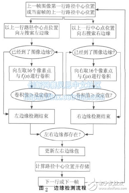
The implementation of the two convolution functions in Figure 2 on the hardware is
It can be seen from the above formula that V1 and V2 have a value range of 8 to 16, so it is defined as a path edge point criterion when the convolution value is greater than or equal to 12. When the left and right edge search ends, the center point and path width of the line path are determined according to the following rules. Note that the center point of the previous line is M0, the left edge position scanned is L, and the right edge position is R. The path center point position M and path width W of the current line are calculated as follows:
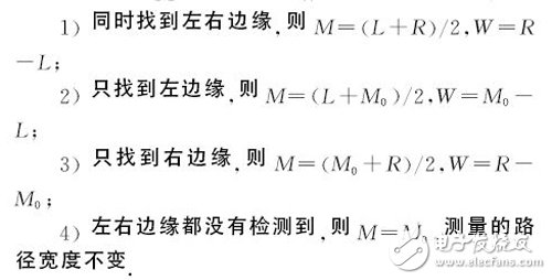
Among the above 4 points, except for the 4th), the remaining 3 points are adjusted for the threshold and the predetermined path width. We use the center position and width of the first line of the previous frame image as the preset values ​​for the center position and width of the next frame image.
2.2 Route Planning The camera on the trolley is fixed and its field of view is fixed. Figure 3 shows the field of view and relative position of the camera, where the trapezoidal frame is the field of view, the y-axis is the car's heading direction, O is the car's front axis center point, and D is the farthest path's center point, the target point. The planned route is an arc that passes through the O and D points and is tangent to the y axis. In the case that the car deviates from the path, the planned route can guide the car to gradually return to the navigation path. According to the geometric relationship given in Fig. 3, it can be concluded that the radius of curvature R of the planned path satisfies the equation
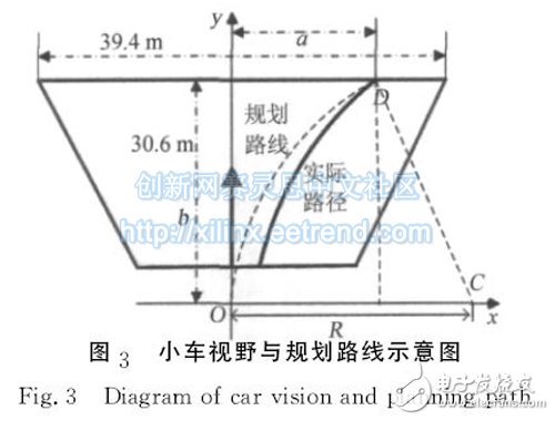
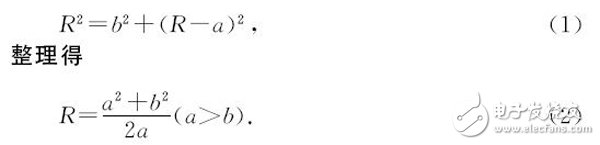
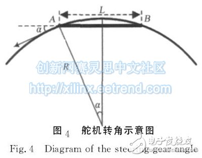
Figure 4 shows a schematic diagram of the car traveling on an arc. The two points A and B respectively represent the center point of the front and rear axles of the car, and L is the length of the main shaft of the car. From Fig. 4, the relationship between the steering angle of the steering gear of the car and the radius of curvature R of the planned route can be obtained.
Sinα=L/2R. (3)
Since the radius of curvature R of the actual route is much larger than the axle L in the actual walking route, the equation (3) can be simplified to α≈L/2R. (4)
According to the angle calculated by equation (4), the steering angle of the trolley can be controlled in real time. The car in the experiment uses a pulse modulation (PWM) controller to control the steering angle. The steering angle is proportional to the duty cycle of the output to the controller, with α=μx, (5)
Where x is the duty cycle and μ is the scale factor.
It can be known from equations (3) to (5) that the duty ratio of the steering angle of the steering gear is proportional to the curvature of the planned route.
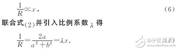
Since b is kept unchanged during the navigation process, it is only necessary to measure the abscissa value a of the target point D in the field of view, and the duty ratio required for the control can be obtained according to the equation (7), and the navigation of the trolley is realized. And control.
Ren Yongxin et al. [14] also adopted the circular route planning, but the distance between the midpoint of the front axle of the trolley and the pre-pointing point is the route parameter, which is not conducive to calculation, and the formula we give is more conducive to obtaining directly on the image. It is more convenient for real-time calculation. In the traditional fuzzy control, the path is controlled by segments and types. The control is discontinuous and inaccurate, and the arc route planning algorithm proposed in this paper has the advantage of continuous and precise control.
Zcash Mining Machine:Bitmain Antminer Z15,Innosilicon A9 ZMaster,Bitmain Antminer Z9 Mini,Bitmain Antminer Z11,Innosilicon A9++ ZMaster,Innosilicon A9+ ZMaster,Bitmain Antminer Z9
Zcoin is a digital currency that aims to create a truly anonymous method of trading.
One big obstacle to Bitcoin's emergence as an electronic currency is that all its transactions are visible on a public blockchain. As a result, Bitcoin's interchangeability has been controversial. Some people or companies (mainly exchanges) will not accept bitcoins for certain addresses. Such scrutiny runs counter to Bitcoin's core philosophy.
Zibo is the latest attempt to create a currency that can be verified without knowing the input and output of a cryptographic signature. This is called a zero-knowledge proof. DASH and Monero are two other digital currencies that are also trying to solve the same problem using different encryption methods.
The whole world is buzzing about zeros. A lot of people respect the Zibo development team. They have received investments from prominent Bitcoin venture capital firms such as Pantera, Distributed Capital, and Digital Currency Group. Bitcoin luminaries such as Roger Ver, Erik Voorhees, Barry Silbert, and Li Xiaolai have invested in Zcoin out of their own pockets. Confirmation bias is an important factor in why investors choose one project over another. If the leading players in the bitcoin industry are investing, it must be a good thing, right?
Unfortunately, Zcoin did not issue an initial currency offering (ICO) to investors. ZEC is the three-digit currency code for zerocoin. ZEC will initially be mined, just like Bitcoin. But unlike Bitcoin, which was full of unknowns when it was first launched, ZEC's founding block is a high-profile one. ZEC prices have skyrocketed because of extreme demand.
Zcash Mining Machine,Z15 antminer,antminer z11,zec Asic miner,zmaster
Shenzhen YLHM Technology Co., Ltd. , https://www.ylhm-tech.com