
Display technology is moving in the direction of large screens, high definition, high brightness and high resolution. In general, a display with a screen display face line size of 1 meter (40 inches) or more is called a large screen display. As an important display device, the projector has been widely applied to many fields such as finance, education, enterprise, and military. The large-format and high-definition multimedia presentation function it has has made the information transfer more effective. At present, the mainstream products on the market are three-chip LCD projectors and DLP projectors, among which the market share of three-chip LCD projectors is as high as two-thirds.
However, the vast majority of projector buyers are government departments, companies, and universities. Whether it is a three-chip LCD projector or a DLP projector, its high price has always prevented the projector from entering the average home. In order to simplify the equipment structure and reduce the cost, this paper presents a design method of FPGA-based high-efficiency monolithic color LCD projector.
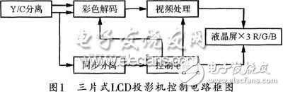
1 Projection principleThe general circuit principle of the three-chip LCD projector is shown in FIG. As can be seen from FIG. 1, the circuit principle of the conventional LCD projector is to pass the transmitted video signal through color decoding to generate R, G, B signals, and then load the three primary color signals in the red and green through the video processing circuit. The three blue monochromatic LCD screens are finally added to three monochromatic projection tubes, and after being restored by three monochromatic projection tubes, the images are then magnified several times by the optical lenses and reflected by the mirrors onto the screen. Finally, a color image is synthesized on the screen. It can be seen that since the three projection tubes and the projection lens are not all placed on the screen, the optical paths through which the three image signals are restored to the screen are different, and this inevitably leads to the three-color signals R, G, and B in the The screen cannot be completely reunited, causing convergence distortion.
Therefore, this article starts with the video processing circuit and control circuit of Figure 1 and designs a new projection method that displays R, G, B three-colored monochromatic image data on a liquid crystal screen and illuminates the incoming R The monochromatic light is modulated by G, B, and then processed by an optical system such as transmission, refraction, and image stretching. Finally, a color network image is formed on the screen. The principle of the method is shown in FIG. 2.
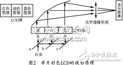
It can be seen from Figure 2 that the biggest feature of this count is the display of R, G, and B primary color images on an LCD screen, and projection by modulating the monochromatic light, unlike the traditional projection system. Use three LCD screens to display the R, G, B color images.
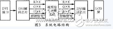
2 projector system circuitIn the projector design, the role of the control circuit is to process the input video and digital image signals to convert them into signals suitable for LCD screen display. The circuit part of the projection system is shown in Figure 3. When the image signal is transmitted from the DVI interface to the DVI decoding chip, the system can decompose the video signal into 24-bit R, G, B monochrome signals and corresponding control signals, and then perform the relevant conversion through the video signal processing circuit composed of FPGA, and then After DVI encoding chip to restore DVI signal, finally sent to the LCD screen.
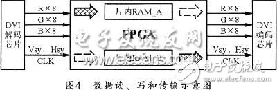
It can be seen from the schematic diagram of the system circuit. The signal processing circuit with the FPGA as the core (including the DVI decoding and encoding chip) is the most critical part of the entire design. Figure 4 shows the data read/write and transmission diagrams. The data from the DVI decoder chip into the FPGA includes 8-bit parallel R/G/B signals and row, field control signals and clock signals. In fact, to achieve real-time video display, one frame (the highest resolution supported by the author's LCD screen is XGA, 1024 & TImes; 768) should be processed. However, if the entire frame of data is processed together, at least 2 MB of external memory is required to buffer the data, which increases the cost and increases the complexity of the circuit. Therefore, in this design, the author adopted a new idea, that is, the input video data is processed line by line, and “Ping Pong operation†is used in the data flow processing of two adjacent lines, so that real-time display can be realized. It also simplifies the circuit. The specific operation is as follows:
1 The FPGA's on-chip RAM is divided into "RAM_A" and "RAM_B" by module calls;
2 In the first line cycle, the first input data stream is buffered to "RAM_A": Because a line of video signal has 3K bytes, in order to achieve separation of the three primary colors on the LCD screen, when storing data, The data is stored in the order in which the data enters the FPGA, and the red data should be sequentially stored in the first to 1024th storage units, the green data in the 1025th to 2048th storage units, and the blue data in the 2049th to 3072nd. Storage unit, which means that the original pixel is "disordered" to store;
3 In the second line period, the second line of video signal is stored in “RAM_B†as described in step 2, and the first line of video signal stored in “RAM_A†is read from the I/O port in sequence. After being encoded by the DVI encoding chip, it is sent to the LCD screen, that is, it reads data "in order";
4 Repeat steps 2 and 3 to alternate read and write operations between RAM_A and RAM_B until one frame of data has been transferred.
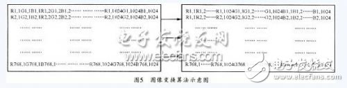
At this time, the specific algorithm for displaying data on the LCD screen is shown in Figure 5, that is, R1,2 occupy the position of G1,1 (that is, the second element), R1,3 occupy the position of B1,1 (that is, the third element ), R1, 4 occupy the fourth unit, and so on, until 1024 red data is arranged on the LCD screen, and then start the green data, followed by blue data. In this way, the purpose of displaying the R, G, B images on an LCD screen in FIG. 2 can be achieved.
The FPGA used in this design is EP1C6Q240C8 in Altera's CvclONe series. The FPGA has an on-chip memory capacity of 90 kbits and is fully capable of processing video signals with a resolution of XGA display mode. If you want to support higher resolution projection modes or perform full-frame image processing, simply replace the FPGA with larger on-chip RAM resources or external memory on the FPGA I/O port. The DVI decoding and encoding chips use Sil161 and Sil164, respectively.
In addition to the video signal processing of the projector, the FPGA-based controller can also be applied to flipping, intercepting, and pixel extraction of flat panels. The key to its operation is the control of data read and write addresses.
3 LCD screen processing and optical adjustmentThe TFT liquid crystal panels on the market today have a color filter film. In this design, if this type of liquid crystal panel is directly used, when R, G, and B three monochromatic lights respectively illuminate the R, G, and B image areas, the color filter film absorbs a large part of the light energy and thus the brightness of the projection light. Too low to meet application requirements. Therefore, the liquid crystal panel used in this design needs to remove the color filter film or the product without the color filter film, in order to increase the light source utilization and projection brightness.
Because the video signal is divided into three parts: R, G, and B on the LCD screen, after the three primary color images are converged by the liquid crystal panel, a height equal to the original image is formed. A color image that is one-third the width of the original image. At this time, only a wide-screen lens is required to widen the compressed image so that it can be restored to a normal image.
4 ConclusionWith the popularity of the concept of home theater, more and more consumers expect to enjoy the powerful shock of making movies at home. However, expensive projectors have deterred many families. This paper starts from the practical application and designs a high-efficiency single-chip color LCD projection method based on FPGA. It is not difficult to see that the projection system will have the following advantages:
(1) Once commercialized, the cost of this new type of projector is much lower than that of other LCD projectors, making it easy to enter ordinary families;
(2) High integration, small volume, large information capacity, and high speed;
(3) Significant increase in light utilization, which improves display quality.
Manual Hydraulic Valve Remote Control Device
The manual valve remote control device consists of a fixed manual hydraulic pump, a hydraulic driver and a butterfly valve. The device takes a single valve as the remote control operation object, and has the characteristics of compact structure, simple operation, convenient operation and maintenance, etc. It is suitable for remote opening and closing control of special position valves in oil tankers, chemical tankers, oil platforms and other ships.
marine Controls device,Manual hydraulic valve remote control device,black marine controls device
Taizhou Jiabo Instrument Technology Co., Ltd. , https://www.taizhoujbcbyq.com