
Design of Automobile Anti-collision Alarm System Based on Single Chip Computer
With the continuous social and economic progress and the rapid development of high technology, in daily work and life, cars have become an ideal means of transportation. While the car brings convenience to people, it also causes frequent traffic accidents, which results in casualties and loss of economic property. Therefore, the safety of car driving has become the focus of attention. Car crash safety technology is the most difficult and core part of car safety technology. Analysis of road traffic accidents shows that more than 80% of car accidents are caused by the driver ’s unresponsiveness, and more than 65% of vehicle collisions are rear-end collisions. , The rest belong to side collision. In order to reduce the occurrence of car accidents and provide a sense of security to users who own cars, we have developed a simple and reliable safety system that can automatically detect the distance and find an alert to the driver when the distance between the car and the obstacle is less than the safe distance. Practical meaning. Because ultrasonic testing has the advantages of fast accuracy and so on, therefore, this design uses an ultrasonic testing chip to realize the collision warning function.
1 Automobile anti-collision alarm hardware design
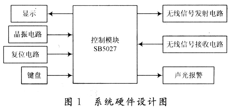
According to the product cost performance and actual needs, the intelligent ultrasonic ranging integrated circuit chip SB5027 developed by Zhongyi Electric Measurement Research Institute is used. It adopts CMOS manufacturing process, with a comparator on the chip, a standard 40 kHz ultrasonic generator and echo response pulse reception The device integrates functions such as dynamic digital display information output, operation keyboard, data storage, and parameter setting. When using SB5027 for distance detection, it has the following characteristics: dynamic digital tracking display; can set parameters such as upper limit, middle limit, and lower limit of distance; can allow parameter setting for distance, time, timing and other alarms; maximum range and minimum resolution Rates are set by the user; support value-added ranging function. The system hardware structure design is shown in Figure 1. The system is composed of ultrasonic transmitting circuit, ultrasonic receiving circuit, keyboard display circuit, core function chip, auxiliary circuit (reset circuit and crystal oscillator circuit) and alarm circuit.
1.1 Principle of ultrasonic distance measurement
The basic principle of ultrasonic ranging is basically the same as that of sonar echolocation method. The ultrasonic generator continuously sends out 40 kHz ultrasonic waves. When encountering obstacles, it reflects back the reflected waves. The ultrasonic receiver receives the reflected wave signals and converts them into electrical signals. By measuring the time difference T between the transmitted wave and the reflected wave, the distance can be obtained:
S = (1/2) CT
Where: C is the speed of ultrasonic sound, and:
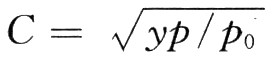
In the formula: y is the adiabatic volume coefficient of the gas (air is 1.4); p is the gas pressure (sea level is 1.013 × 10⁶Pa); gadolinium is the density of the gas (air is 1.29 kg / m3).
For 1 L of air, the mass is m, the volume is v, and the density p = m / v.
Therefore:
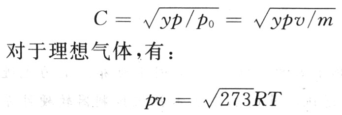
In the formula: R is the molar gas constant; T is the absolute temperature.
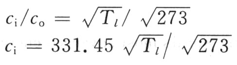
Since y, R, and m are all known constants, the speed of sound C is only related to temperature. If the temperature T is unchanged, the speed of sound in air is independent of air pressure. At 0 ℃, C0 = 331.45 m / s. For any temperature, there are:
1.2 Sound and light alarm, wireless signal transmission and receiving circuit design
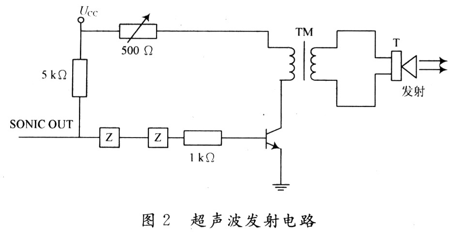
Automobile anti-collision alarm detection uses ultrasonic sensors. The ultrasonic sensor is composed of an ultrasonic transmitting circuit and an ultrasonic receiving circuit. The ultrasonic transmitting circuit is composed of Schmitt trigger, transformer and transmitting sensor T probe. Because there is a standard 40 kHz ultrasonic generator inside the SB5027, the internal signal is directly quoted (leaded out from the pin SONICOUT), but the signal is weak, and the signal must be amplified in the transmitting circuit. This signal is connected in series through two Schmitt reverse flip-flops, and at the same time, the NPN transistor VT is turned on through the voltage dividing resistor, and the voltage pulse signal at the output terminal is fed back to the transformer, and the voltage signal is increased through the boost transformer To drive the transmitting T40 sensor to emit 40 kHz ultrasonic waves, the circuit diagram is shown in Figure 2.
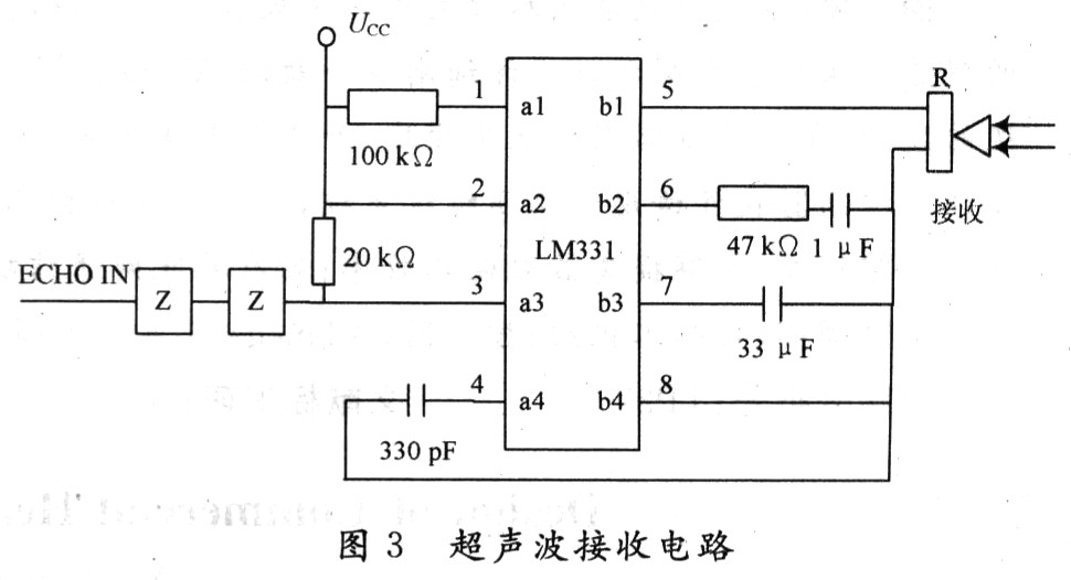
Ultrasonic signal receiving and processing is one of the key technologies of the ranging system. Because the ultrasonic receiving circuit amplifies the weak signal output by the probe to drive enough to control the subsequent circuit, the receiving circuit mainly solves the phenomenon of diffuse reflection on the surface of the received signal, so the receiving circuit mainly solves the stability of the received signal, that is, the received signal Automatic gain control problem. The part of the transmitted signal that is in contact with the surface of the object is relatively weak, and at the same time, the unequal amplitude of the reflected signal will be caused due to the distance of the measured distance. In order to eliminate the effects of the above defects, the receiving circuit should have signal amplification and automatic gain control functions. The chip LM331 is selected in the design to complete the replacement of voltage / frequency. The ultrasonic receiver R converts the received reflected wave into a voltage through the LM331 after filtering through the capacitor and resistance, and then connects the two reverse Schmitt triggers in series to amplify and shape the voltage from the LM331 and send it to the ECHO of SB5027. IN end, the circuit diagram is shown as in Fig. 3.
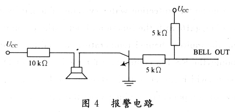
When the alarm circuit exceeds the range, the BELLOUT terminal of SB5027 outputs a high level to turn on the transistor VT1, connect the alarm to the power supply and emit an alarm sound. The circuit diagram is shown in Figure 4.
Software system design
The design flow chart of the alarm software is shown in Figure 5.
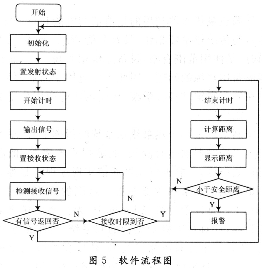
After the system is powered on, the main program completes the initialization work, including the initial value of the memory. When the car is in working state, the alarm devices placed in front of and behind the car will collect the field signal and send it to the SB5027 single-chip microcomputer. The signal received by the single-chip microcomputer is processed, calculated, and compared. When normal, the alarm does not alarm; if the limit is exceeded when compared with the lower limit, an audible and visual alarm signal is generated to remind the driver to take corresponding measures.
3 Conclusion
The car anti-collision alarm of this design makes full use of SB5027's internal resources for data processing and time control functions, so that the system works in the best state and improves the system's comprehensive response sensitivity. The alarm is timely and the anti-collision function control is realized. Practice has proved that the system is better than other alarms, and has the characteristics of small size, convenient use and simple operation.
4.5Mm Ribbon Connector,El Connector,El Wire Connector,Compact El Connectors
YUEQING WEIMAI ELECTRONICS CO.,LTD , https://www.weimaiwafer.com