
Liu Zhen, Beijing Quanlu Communication Signal Research and Design Institute Co., Ltd.
Keywords: signal system; logic unit; Ethernet
1 Overview
With the development of modern railway signal technology, the types of ground control systems belonging to different applications have become more and more diversified, such as interlock systems, train control centers, wireless blocking centers, temporary speed limit servers, and automatic train monitoring centers. These systems all require a reliable and secure logic control unit.
At present, the logical computing units used by various manufacturers in the above systems are:
1) General industrial control machine combination;
2) Standard CPCI cage combination;
3) General server combination;
4) Embedded carrier board assembly.
The above-mentioned combination structure has the following problems to varying degrees:
1) IPCs and server hardware motherboards are updated too quickly and the system software needs to keep up to date, which is not conducive to the stability of software versions.
2) IPCs and servers mostly have fans, and they have strict requirements on the ambient temperature, and the maintenance workload is large in the later period.
3) Data communication mostly uses parallel buses, such as ISA, PCI, VME, etc., and has limited data throughput capability.
4) The embedded onboard module has limited computing power.
2 logic operation unit works
2.1 Logical Unit Operation Model
In order to describe the problem simply, after ignoring the external device, the logical operation unit is abstracted and modeled as shown in Fig. 1. The logical operation unit of the signal system mainly performs three tasks: data input, security operation and result output. In order to ensure data communication security, data input must adopt secure communication protocol to prevent communication data from the two dimensions of data accuracy and timeliness. After the operation, the result data is output by the output channel after two security comparisons.
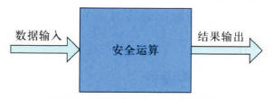
Figure 1 How Logical Units Work
2.2 Logic Unit Features
As the control core of the signal system, the computing unit has its own characteristics, mainly in:
Security requirements must meet the requirements of fault-oriented security. In the system structure, two or two or three redundant structures must be adopted to eliminate the security risks caused by single point of failure of hardware and software.
Computing performance requirements, the control logic of the signal system is more and more complex, and at the same time the security communication protocol needs to be encoded and decoded, so its CPU must reach a certain processing capacity.
Data communication throughput requires that more and more equipments are controlled by the ground control system. Most of the control software adopts a periodic execution method. As far as possible, it needs to communicate with other equipment in each cycle, and a high-speed and reliable communication channel is indispensable.
Reliability and environmental adaptability requirements, logical computing unit should have high reliability, reliability will reduce significantly improve the security. In addition, the signal system's working environment is complex, and the hardware system must have a certain degree of noise immunity, and it can work normally under high temperature, low temperature, humidity, vibration and other environments.
2.3 Communication Interface
With the continuous improvement of related safety communication protocols, the reliability of Ethernet standard equipment has increased, and more and more railway communication systems use internal Ethernet communication. Ethernet networking is convenient, and long-distance transmission also has mature industrial products. The logic operation unit obviously has to have a high-speed and reliable Ethernet interface to facilitate system function expansion.
3 logical computing unit hardware architecture design
3.1 PC104 based computing unit
The PC104 standard was produced earlier, its peripheral matching circuit is simple in design, and the modular expansion function is convenient. At present, it has been applied in the operation unit of many signal systems. However, due to its parallel data bus ISA or PCI, its computing performance and data communication throughput capacity are limited.
3.2 COM Express Technology
COM Express is a computer module standard defined by the International PICMG Association. It is a highly integrated single-board computer and is particularly suitable for implementing custom industrial computer solutions. It is suitable for standard single-board computers due to their structure or lack of scalability. When not suitable for use, in the COM Express standard abandoned the previous low speed PCI, IDE signal, is a standard based on a new high-speed computer interface, PCI Express, Serial ATA, Gigabit Ethernet, and PC104 standard phase Compared with the data throughput, the data throughput is greatly improved.
Architecturally speaking, COM ExpresS can be understood as a Highly Integrated CPU and its minimum system into a Module, and this module can be extended through a standard interface COM Express defined a custom-designed specialized Board (Customized Carrier Board) So as to constitute a product or system.
3.3 COM Express-based computing board
Using a standard COM Express module with a small number of peripheral circuits, the board function can be calculated. As shown in Figure 2, using the COM Express type 6 standard module, comes with 6 PCI Express x1 interfaces, using Intel's 82583 chip to expand the multi-channel Gigabit Ethernet interface, and the other SATA interface can be directly extended CFast memory card for loading Operating system files and applications. Due to the limited number of GPIO modules, an FPGA can be used to read configuration information such as system ID and CPU ID, and can also be used to output LED indicator information.
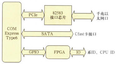
Figure 2 COM Express-based computing unit
As shown in Figure 3, the network card chip 82583 integrates the PHY and the MAC, which can effectively reduce the number of on-board devices and reduce the PCB layout complexity. The 82583 communicates with the CPU module through the PCIe x1 interface. The data transmitted on the PCI Epress bus is an LVDS high-speed differential signal. The receiving and sending each occupy a pair of data lines. The channel's unidirectional data rate is 2.5 Gbit/s.
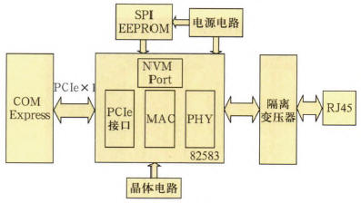
Figure 3 Ethernet interface expansion circuit
The 82583's operating clock is provided by a 25 MHz crystal. This clock is internally clocked to provide timing signals for Gigabit Ethernet. In addition, in order to ensure the normal operation of the 82573, an external EEPROM is required through the NVM interface for power-on initialization of the 82583.
3.4 Two-by-two-two redundant model design
As shown in Fig. 4, a complete set of ground logic operation units consists of mutually redundant dual systems. Each system has two independent CPU modules, and high-speed Ethernet channels are used for intra- and inter-system communication. Because the system adopts the Ethernet channel for data exchange, in order to reduce the board complexity, the two CPU boards in a single system are no longer integrated in the same board, but are divided into two separate boards.
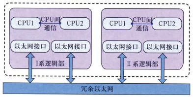
Figure 4 Two-by-two-two redundant architecture
As shown in Figure 5, the logical computing unit adopts a 6U standard cage structure, and the two systems are integrated in the same cage. The intra- and inter-system Ethernet networks are connected directly through the backplane, eliminating the need for wiring outside the board. The interface expansion board in the figure is used to extend other communication interfaces via Ethernet for adapting non-Ethernet connection signal devices. The functions of the CPU board are the same and are interchangeable. The ID is determined by the slot, and the software determines that it performs different tasks.
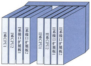
Figure 5 logical computing unit mechanical structure
4 computing unit software design
4.1 Operating System Selection
With the increase of CPU frequency and the increase of memory, DOS systems have become less and less able to support the latest and highest performance hardware. Especially for high-speed CPU external communication bus, such as PCI, PCIe, USB, etc. can not be directly supported, users need to develop the relevant interface driver, the workload is relatively large.
The operating systems such as Linux and VxWorks that have emerged in recent years all have good support for high-performance CPUs and the latest external buses. However, because the Linux operating system is an open source system, its internal code source channels are complex and have not been uniformly tested and verified. It's hard to guarantee.
VxWorks Cert platform is a real-time security operating system specially developed by Wind River in recent years for aviation, railway, medical and other security applications. It complies with IEC 61508 SIL 3 requirements, and provides relevant evidence documents to reduce user safety certification workload.
Based on the above reasons, the system uses VxWorks as the operating system of the computing unit. In addition to directly obtaining the driver code of the relevant peripherals, the VxWorks Cert version also provides the relevant evidence documents required for safety certification, reducing the overall system safety certification workload and accelerating the New product listing pace.
4.2 Software System Working Model
The computing unit is a two-by-two, two-by-two security processing platform. The dual-system operation is performed by one of the systems as the main system to complete all the operations and communication functions of the system, and the other is used as a redundant shadow system. In order to simplify the problem, a single-system single CPU is taken as an example to describe the working model of the software system.
As shown in Figure 6, the top-down sequence of the system is: application software, system software, operating system, driver layer, hardware physical layer, and communication control objects (such as IO, control display, monitoring, and other Ethernet devices).
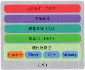
Figure 6 System working model
The system software realizes the communication data exchange between CPUs in the system and completes the operation of two, and the application software is only responsible for the application of logic operations. This has the advantage of making the application software structure framework simpler and ignoring the intermediate transmission channels of data, making it an end-to-end data communication experience.
4.3 Two-by-two-two-software implementation principle
The operation of the logic operation unit CPU is mainly to periodically perform safety logic processing on the data input by the Ethernet, and output the calculated data to the external through the Ethernet. As shown in FIG. 7 , the two-by-two calculation in each logical operation cycle mainly includes the following steps:
1) The dual CPUs in the department obtain external input data through their respective external Ethernet channels;
2) The dual CPUs in the system exchange the input data received in this cycle;
3) Compare the exchanged data;
4) Send more consistent data to the logic calculator to generate pre-outputs;
5) CPU asks for exchange of pre-output result data;
6) Compare pre-output data;
7) Send more consistent output data over Ethernet.
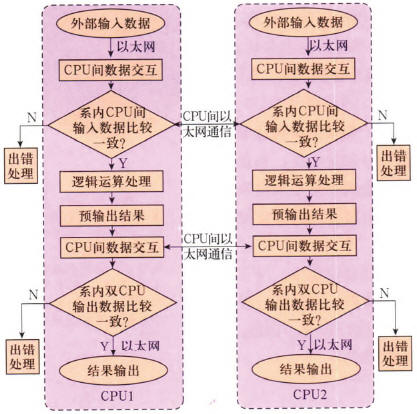
Figure 7 The working principle of dual CPU in the system
4.4 Intra- and inter-system data interaction mechanism
From the perspective of engineering applications, developers hope that more and more data can be exchanged and compared within a single cycle within the application software system and between systems. At present, most signal system computing units use fixed-capacity DPRAM for intra-series or inter-system data. Exchange, removes the data interaction overhead of configuration and system software, and the capacity available for application software is very limited. The system described in this article will use a high-speed Gigabit Ethernet interface as the channel for dual-CPU interaction in the system, which can meet the increasing demand for dual-CPU data exchange for application developers in a certain period of time.
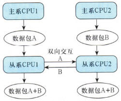
Figure 8 Principle of data interaction between systems
As shown in FIG. 8 , taking the data exchange between systems as an example to describe the logic unit security redundancy processing mechanism, the workflow in a communication cycle is as follows:
1) The main CPU1 sends "Data packet A" to the slave CPU1;
2) The host CPU2 sends "Data packet B" to the slave CPU2;
3) From the system CPU1 will receive the "packet A" directly copied and sent to the slave CPU2;
4) from the Department of CPU2 will be received directly "packet B" copy sent to the slave CPU1;
After the above four steps, “two data packets A+B†are obtained from the two CPUs in the system. Since the direct-connected high-speed Gigabit Ethernet is adopted for inter-CPU communication in the system, the data throughput capability is significantly improved and the communication delay is improved. At the same time, it is also reduced, so that each CPU has the ability to communicate redundantly.
5 Conclusion
This text has designed a kind of logical operation unit based on COM Express module, utilizes PCIe bus to expand Ethernet interface extensively, have improved the data handling capacity of the arithmetic unit greatly, reduced the resource consumption of the CPU in communication effectively, offer the overall operation performance.
Pen Electronic Cigarette,Pen Style Electronic Cigarette,Mesh Coil Disposable Electronic Cigarette,Disposable Electronic Cigarette
Jinhu Weibao Trading Co., Ltd , https://www.weibaoxd.com