
Micromechanical inertial devices are an important research content of MEMS, and micro-inertial devices include micro-gyro and micro-acceleration sensors. The micro-acceleration sensor manufactured by MEMS technology is superior to the conventional acceleration sensor in terms of life, reliability, cost, volume and weight, making it widely used in both civil and military fields. This article is a low-power, fully functional dual-axis accelerometer from ADI. As a sensor for slope measurement, ADXL202E gives an example of the design of the slope measurement system composed of ADXL202E and single-chip AT89C52.
1, ADXL202E features
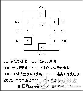
The ADXL202E is a low-cost, low-power, fully-featured, monolithic integrated circuit that combines dual-axis accelerometers. It measures both dynamic and static accelerations with a measurement range of ±2g. It has both an analog signal output and a pulse width duty cycle output. The ADXL202E can withstand up to 1000g of severe impact. Figure 1 shows the pinout and pin functions of the ADXL202E.
2, the principle of measurement
The ADXL202E is a complete dual axis acceleration measurement system based on a single integrated circuit. It is an open-loop acceleration measurement structure that operates on a polysilicon-based micro-motor sensor and signal control loop. For each axis, the output loop converts the analog signal to a digital signal with a pulse width duty cycle. These digital signals interface directly with the microprocessor. The ADXL202E measures positive and negative acceleration with a maximum measurement range of ±2g. The ADXL202E also measures static acceleration and can be used as a slope measurement. The sensor uses a polysilicon structure that is micromachined on a silicon wafer, supported by elastic elements of polysilicon and provides the resistance needed to balance the acceleration. Structural deflection is measured by a variable capacitance consisting of a separate fixed plate and a central plate attached to the moving object. The fixed plates are controlled by every p phase of the square wave. The accelerometer changes the balance of the variable capacitor after receiving the acceleration force, so that the amplitude of the output square wave is proportional to the acceleration. The phase demodulation technique is used to extract information to determine the direction of acceleration. The output of the demodulator is output to a pulse width duty cycle demodulator through a fixed 32 kW resistor. At this time, the user is allowed to change the size of the filter capacitor to set the bandwidth of the output signal. This filtering improves the accuracy of the measurement and effectively prevents frequency aliasing. After low-pass filtering, the analog signal is converted to a pulse width duty cycle signal by DCM. T2 is set in the range of 0.5 ms to 10 ms by a resistor RSET. The output duty cycle is 50% at 0g acceleration. Acceleration can be measured by a count/timer or low power microcontroller by measuring T1, T2.
The analog output signal can be obtained in two ways: one from the XFILT and YFILT pins; and one from the dc value obtained by filtering the pulse signal through the RC filter.
1, filter design
The ADXL202E measures static acceleration as well as dynamic acceleration with a maximum measurement bandwidth of 5000 Hz. The bandwidth (W) is determined by the parameters of the low pass filter. The RFILT (filter resistance) can be varied within ±25% of the nominal value of 32 kW, and the bandwidth is correspondingly changed accordingly. In this design the RFILT is 32 kW. Therefore, the bandwidth of the acceleration signal is set by the external capacitors of the XFILT and YFILT pins. Capacitors must be mounted close to the pins for aliasing and noise suppression. The 3dB bandwidth calculation formula is as follows:
F(-3dB)= 1/2P[32kW&TImes;C(X, Y)]
Namely: F(-3dB)= 5mF/ C(X, Y) (1)
The smaller the visible capacitance is, the wider the signal bandwidth and the higher the resolution. C(X, Y) is the capacitance value of the filter, and the bandwidth C(X, Y) is mainly determined. In addition, in any case, the minimum capacitance value of C(X, Y) is 1000pF. In this design, C(X, Y) is selected to be 100nF, that is, the acceleration analog signal bandwidth is 50Hz.
The noise characteristic of the ADXL202E is the same large white Gaussian noise at all frequencies, in mg/  For the unit, the noise is proportional to the square root of the acceleration signal bandwidth.
Typical noise values ​​for the ADXL202E can be calculated using the following formula:
Noise(rms)=(200mg/ )&TImes;  (2)
(2)
Since the acceleration signal bandwidth is 50 Hz in this design, the noise mean square value is 1.79 mg.
Therefore, the XFILT and YFILT pins of the ADXL202E are connected to a 0.1mF capacitor so that the analog output bandwidth is 50Hz and the output noise is 1.79mg. At the same time, the XFILT and YFILT pins of the ADXL202E generate an analog signal that corresponds to the slope.
The gravity component induced by the ADXL202E varies between +1g and -1g. At 0g, there are:
OFFSET (offset band) = 2.5V ± 0.4V (5)
SensiTIvity (sensitivity) = 167 mV / g ± 17 % (6)
2. The cycle setting of DCM:
Use RSET to set the period of the DCM: The period of the DCM with two channels is set by the resistor RSET. The formula is: T2 = RSET (W) / 125 MW. The device can operate in the range of 0.5ms to 10ms. In this design, the RSET is selected to be 330 kW, that is, the DCM period is 2.64 ms. RSET should be mounted close to the T2 pin to minimize distributed capacitance.
3. Analog signal processing circuit
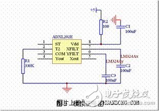
Due to the influence of the internal 32kW resistor of the ADXL202E, the analog output drive power of XFILT and YFILT is insufficient. Therefore, a follower consisting of LM324 operational amplifiers is required after XFILT and YFILT to increase the drive. The analog signal diagram of the ADXL202E can be obtained by the component parameters selected above, as shown in Figure 2.
4, parameter calibration
Gravity systems are the most stable, accurate, and widely used frame of reference for slope measurements. By aligning the direction of the device with the horizontal plane, a calibration value of 0 g is obtained.
Due to the difference in device parameters, the basic parameters of the chip and the two different axial parameters of the same device also differ. Therefore, when the measurement accuracy is required to be high, the typical value of the parameter is still used to cause an error.
To improve the accuracy of the measurement, it is necessary to carefully calibrate the relevant parameters before the measurement. If the gravity vector is used as a reference, the measurement range should be set between 1g and -1g. When the X(Y) axis points to 1g, the output of the sensor is the maximum value, denoted as A; when the X(Y) axis points to -1g, the output of the sensor is the minimum value, denoted as B. Then the calculation sensitivity SensiTIvity formula is:
Sensitivity
 (7)
(7)
The design of the single-chip computer system is divided into two parts: the lower computer and the upper computer. The lower computer adopts the commonly used AT89C52 as the processor, and the analog-to-digital conversion adopts TLC1543 with 10-bit precision as the A/D conversion device, adopts X5045 as the watchdog chip, and the voltage regulator uses LM336. The upper computer is designed with Visual Basic 6.0, which mainly includes parameter calibration and real-time monitoring interface design.
1, A / D conversion circuit design
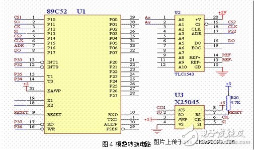
The gravity component of the ADXL202E varies between +1g and -1g, while the supply voltage of the sensor ADXL202E is +5V, so the linear variation of the output analog is between +2.1 and +2.9V. In order not to lose the sampling accuracy of the A/D converter chip TLC1543, the REF+ terminal of the TLC1543 is connected to +3V, and the REF- terminal is connected to +2V. In order to get the regulated power supply, the LM336 chip is needed to obtain a stable voltage of -5V, and then a negative feedback amplifying circuit is formed by the operational amplifier LM324, and finally the +3V and +2V required by the reference source are obtained. Its circuit is shown in Figure 4.
2, watchdog circuit design
The system uses a serial X5045 chip as the watchdog chip. When the chip is powered on, when the power supply voltage exceeds 4.5V, RESET changes from high level to low level after a stabilization time of 200mS. At power-down, when the power supply voltage is lower than 4.5V, the RESET signal immediately goes high and remains until the power supply returns to stability. In addition, the EEPROM chip also has a 4096-bit EEPROM, which can be used as a power-down protection storage space for data.
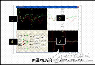
The host computer is designed with Visual Basic 6.0. Mainly complete the design of the monitoring interface, the correct reception of the serial port data, including the ADXL202E parameter calibration, monitoring curve display and other necessary functions.
Figure 3 shows the designed monitoring platform. From Fig. 3, the curves of the pitch angle and the rotation angle with time can be observed. From the 3 points in Fig. 3, the slope of the sensor node can be observed with time between ±180°. Change; from the two points in Figure 3, the acceleration change in milligrams can be observed. Through this monitoring interface, the output signal oscillation of the sensor node due to vibration and the like can also be observed in real time. From the control panel of the monitoring platform from 4 in Figure 3, the sensor parameters can be calibrated through the control panel, and the data output by the sensor in real time can be observed.
For the measured static acceleration, it needs to be converted into the corresponding engineering quantity, which is mainly divided into two cases:
(1) The acceleration values ​​Ax and Ay measured by the X-axis and Y-axis of the two-axis acceleration sensor can be converted into inclination by the following formula:
Pitch angle
 (8)
(8)
Rotation angle
 (9)
(9)
(2) Since the X-axis and Y-axis directions of the biaxial acceleration sensor are perpendicular to each other, it is also possible to measure the inclination of 360° in the full circumference. When the output value of one of the sensors is maximum, the output value of the other sensor is the smallest.
Sixth, the conclusionApplying the above design method and its main points, the measurement of the slope (static acceleration) is realized by repeated debugging, and the intended purpose is achieved. Practice has proved that the ADXL202E is very suitable for measurements with slower frequency changes and less acceleration. On the basis of fully considering various factors, reasonable setting of relevant parameters can achieve good accuracy.
Shenzhen Hengstar Technology Co., Ltd. , https://www.angeltondal.com