
As a smart sensing element, FBG sensors are used to monitor systems with good results. With the application of fiber Bragg grating sensing technology in large bridges, building structures, health monitoring (SHM) and other projects, fiber grating sensing systems with large capacity, strong anti-interference, high sensitivity and low cost are increasingly needed. . The use of multiplexing technology is the basic method for realizing the large capacity of fiber Bragg grating sensing systems.
In the past ten years, multiplexing technology has been researched and applied in the field of large-capacity optical fiber sensing, especially the research on FBG multiplexing technology has received extensive attention. Commonly used multiplexing methods are Wavelength division nlulTIpiexing (WDM), Time Division Multiplexing (TDM), and Frequency Division Multiplexing (Frexney division MULTI Plxenig, FDM). WDM technology is limited by factors such as the bandwidth of the light source and the dynamic range of the physical parameters to be measured. The multiplexing of FBG on a single fiber is limited. WDM fiber based on ASE broadband source.
The capacity of the Bragg sensing system is generally 15-20. In a system based on TDM technology. The light source modulates a series of light pulses of equal interval time, and the return time of the same pulse reaching different grating signals is different, and the signals can be separated in the time domain by components such as optical switches. However, all multiplexed gratings use the same pulse source. The intensity of the source and the attenuation of the grating and fiber transmission determine that the number of multiplexed sensors is less than 10.
The light source based on FDM technology modulates a continuous pulse wave, and the frequency of the pulse changes with time. The return time of the grating signal at different positions corresponds to different frequencies, and the multiplexed signal is separated in the frequency domain. Since the duty cycle of the FMCW technology is larger than that of the TDM technology, the light intensity entering the sensing grating array is larger, so the number of multiplexed gratings can reach several tens.
In order to further improve the multiplexing capability of FBG on a single fiber, it is necessary to improve the frequency band utilization of the FBG network. Therefore, fiber Bragg grating sensing systems based on CDMA technology have attracted great interest. Fiber Bragg Grating sensing system based on CDMA technology is essentially an organic combination of wavelength division multiplexing and code division multiple access technology, so it is also called CDMA DWDM FBG system. CDMA technology has been widely used in the field of communications, but it has just begun to be applied to FBG sensing systems.
A particular advantage of using CDMA technology in FBG sensing systems is that because the correlation technique is used to extract the signals of the special sensors from the composite signal returned by the sensor group, the spectrum of the reflected signals of the sensors is allowed to overlap or even be identical, thus making the sensor The wavelength interval between them is much smaller than that of a normal WDM system, so that the multiplexing capability of a single fiber is greatly enhanced, and dense wavelength division multiplexing is realized. In addition, due to the combined effect of the CDMA technology and related technologies, channel noise and crosstalk of each sensor can be effectively suppressed, thereby greatly improving the signal to noise ratio. Therefore, a large-capacity, anti-interference fiber grating sensing system can be realized. Combine the powerful data processing capabilities of computers and corresponding software with potential low cost features.
1 System principle and key technologies
1.1 How the system works
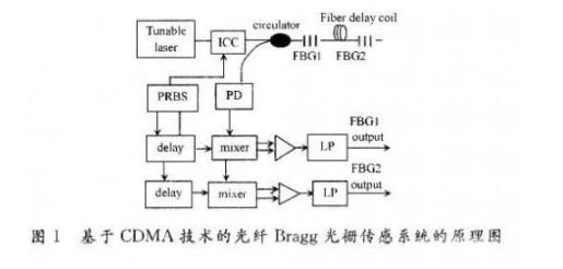
Figure 1 is a schematic diagram of a fiber Bragg grating sensing system based on CDMA technology. The output of the light source is modulated by a pseudo-random sequence code (PRBS), and the FBG sensing array performs a correlation operation on a given PRBS response with the same PRBS delayed for a certain time, and the result is filtered by a low-pass filter to obtain a certain A wavelength-encoded signal that is returned on a particular sensor. After the sensor position is preset and then modulated, the time required for the light source output signal to reach a certain sensor and return to the detector is determined. Therefore, the correlation operation can be determined by appropriately selecting the delay time of the PRBS sent to the correlator. The result comes from which sensor, which can be addressed while obtaining sensory information.
1.2 System key technology analysis
According to the system principle, it can get several key technologies included in the implementation system.
(1) Light source modulation technology. The light source modulation technology mainly includes two aspects: one is to use which pseudo random code (PRBS) to modulate; the second is how to modulate. For the choice of spreading code, it is not a difficult point in the sensing system. This is because the sensing capacity of current practical systems is generally in the range of tens to hundreds, thousands or more, considering that the fiber grating sensing system based on CDMA technology can also be combined with other multiplexing technologies (such as SDM technology). To expand capacity, the m-sequence with good autocorrelation and cross-correlation properties is generally selected to achieve system capacity requirements. For an 8-bit m-sequence, the theoretically achievable sensing capacity on a single fiber is 255. When larger capacity is required, the m-sequence can be extended or by adding a sensing channel.
How to modulate the light source can be analyzed according to the light source. For narrow-line broadband sources, pulse modulation is typically used, i.e., each optical pulse is modulated with a PRBS. For such a light source, the system features high power, and the center wavelength of the sensing grating is relatively concentrated, so it is closer to the characteristics of CDMA technology - the spectrum between the sensing gratings may overlap or even completely overlap, and the relevant technology is used at the receiving end. Distinguish the sensing grating. For the broadband light source, the PRBS driving signal generator is generally applied to the light source through the external modulation interface, and the continuous modulation is performed to modulate the spectrum in the time domain. The system features a DWDM system in combination with WDM and CDMA, which can better utilize the large bandwidth of the light source and CDMA technology to realize a large-capacity system.
(2) Power control technology. Although the capacity, transmission distance, etc. of the fiber Bragg grating sensing system are not worth mentioning relative to the CDMA communication system, this does not mean that the fiber Bragg grating system does not require power control. This is because, on the one hand, the reflection characteristics of FBG will reduce the FBG power behind it in the FBG array, especially if the center wavelength interval between FNGs in the FBG array is not large, when the two FBG spectra overlap, The power of the FBG reflected signal is reduced, so that the correlation processing after the detector is affected by the strong FBG reflection signal, which will eventually affect the accuracy of the despreading; on the other hand, according to the capacity of the CDMA communication system In theory, the CDMA system is a self-interference system, and the factor limiting the capacity of the CDMA system is total interference. The system's capacity is maximized when the following conditions are met, ie, the power is minimized with acceptable signal quality. This is mainly related to the sensitivity, responsiveness, etc. of the detector. The power received by the base station from each mobile station is the same. Therefore, multi-point monitoring should be implemented as much as possible under the condition of good quality. The power control of the fiber Bragg grating sensing system should also be performed so that the reflected power of each sensing grating is in the detector ( Or the relevant processing) is as identical as possible, thereby reducing the occurrence of interference of the weakly reflected signal by the strongly reflected signal.
In the fiber Bragg grating system based on CDMA technology, to achieve power control, it should be considered from the aspects of light source power, optical device insertion loss, grating reflectivity, grating center wavelength and optical transmission loss. Firstly, through theoretical analysis, select optical devices with excellent performance as much as possible, and then combine the test to further adjust the front and rear position of the FBG in the sensing grating and adjust the power of the light source, and select the appropriate coupling coupler to achieve the system capacity and Unification of excellent performance.
2 timing synchronization technology
The previous introduction and system principle have mentioned that the FBG-based fiber Bragg grating sensing system utilizes related technologies to achieve sensor positioning or addressing. However, the autocorrelation property of the PRBS sequence, that is, the same sequence of two relative movements, only has a maximum (larger) correlation value at a certain time point (or a certain period of time), and a correlation value is small in another time period. To accurately address, the key point is to realize the synchronous despreading by sending the PRBS to the corresponding despreading channel after the precise time delay. This technology is related to the success of the entire system, so it is the key technical focus of the system. The easiest way to get timing accuracy is to use a data acquisition card board as an accurate timing device.
3 related processing technology
The correlation processing technique is how to correlate the exactly delayed delayed PRBS sequence with the received signal, and accurately determine which sensing grating signal is based on the magnitude of the correlation value.
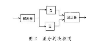
Here, the signal is differentially detected, as shown in Figure 2. In the figure, X denotes a sequence autocorrelation decoder; X denotes a decoder whose sequence is associated with its conjugate sequence. For the m-sequence modulated signal, X is the minimum value (the normalized one is 1) for a certain delay time in one cycle, so that the signal is easily discriminated at the decision end.
4 demodulation technology
The ultimate goal of designing the system is to demodulate the system by using a demodulation method to obtain the offset value of the center wavelength of the sensing grating, thereby deducing the parameter variation of the physical quantity to be measured. How to effectively demodulate is the research focus and difficulty of fiber Bragg grating sensing system, and it is also a research hotspot. There are many demodulation methods, such as interference method, filtering method, and parametric conversion method.
The main discussion here is which demodulation method should be used for demodulation of the fiber Bragg grating sensing system based on CDMA technology. The main factors considered here are:
(1) The system is designed to realize large-capacity sensing, so the demodulation method should be suitable for large-capacity demodulation.
(2) The system uses CDMA technology for addressing, that is, using precise timing and related processing to achieve addressing. Therefore, if the received signal is scanned and demodulated before addressing (such as FP scan demodulation), its influence on timing should be considered.
(3) Since the delay chip is used to distinguish the respective sensing gratings, the chip delay time is generally short (generally at the ms level), especially at a large capacity, such as when the delay time is required to be only 1 chip. This requires the demodulation method to be quickly demodulated, and the demodulation processing speed is greater than the update speed of the input signal, that is, real-time demodulation is realized; or the data of the sensing grating is collected and stored in the time interval, only when needed It is demodulated during demodulation, that is, non-real time demodulation.
In addition, perfecting the manufacturing technology of passive components such as light sources, grating devices and optical couplers, and the packaging technology of fiber gratings are also the basis for improving the performance of the sensing system.
5 Experimental research and analysis of results
5.1 Experimental research
According to the above theoretical analysis, a preliminary experimental study was carried out on the system. The experimental scheme is shown in Figure 3.

In the experiment, the TMS320LF2407DSP development board is used to generate a pseudo-random 3rd-order 7-bit m-sequence with a period of 0.7 ms. After buffer amplification, the ASE broadband source is modulated to generate an m-sequence optical signal and enter the sensing network. The sensor network consists of a fiber grating stress sensor (center wavelength is 1550.84 nm, 3dB bandwidth is 0.217 nm) and a bare fiber grating (center is 1 550.12 nm, 3 dB bandwidth is O.302 nm) Serial build. The photodetector with a response of 0.9 A/W converts the sensing network optical signal into an electrical signal and then sends it into a 12-bit precision data acquisition card in two ways. At the same time, the m-sequence generated by the DSP board is also One channel is fed into the capture card. The optical signals reflected from the fiber gratings at different positions have different time delays due to different transmission distances. By using the excellent autocorrelation and shift correlation characteristics of the m-sequence, the grating can be controlled by controlling the transmission time of the m-sequence at the receiving end. The address is identified.
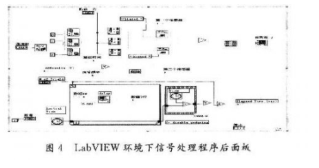
In the experiment, the acquired signals are processed in the virtual instrument software LabVIEW. The specific processing is as follows: Among the three channels of the acquisition card, the first and second channels collect the signal after the DSP passes the buffer drive circuit (one of the signals needs to be delayed); the third channel collects and sends the photodetector The detected signal. The signals of the three channels are sent to the system program under the synchronization node, and the program behind the program is shown in Figure 4.
When the first FBG sensor is directly connected to the optical path and considering the large speed of light, the delay value is treated as 0. Since there is no fiber delay line, the system mainly demodulates this sensor. A 22 m fiber is connected between the second grating and the first sensor, and the delay value is 0.15 ms (the hardware delay is considered in the actual processing, and the delay is set to 2 chips).
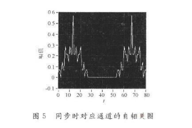
According to the system principle, when the corresponding delay of the channel comes, there is a sharp autocorrelation, as shown in Figure 5. For other channels, the correlation value at the same time is small. As a result, the corresponding sensor grating can be accurately positioned, ie addressed.
5.2 Analysis of experimental results
In the experiment, using LabVIEW to process the acquired signals, the CDMA-based accurate addressing of the fiber Bragg grating sensing system is realized, but there are still some problems to be solved:
(1) In the experiment, the reflectivity of the FBG used is as high as 99%, so it is impossible to achieve addressing when the spectrum overlaps. A further experimental focus is to use FBGS with lower reflectivity to verify the relevant addressing characteristics when the spectrum overlaps; when the spectrum overlaps, when the reflectivity is large, the obtained addressing characteristics are best, and when the spectrum overlaps, the addressing can be achieved. The upper and lower limits of the grating reflectivity.
(2) Although the experiment realized CDMA-based addressing, the ultimate goal of the system-demodulation has not been realized. The literature gives the use of tunable laser scanning for demodulation; the literature provides demodulation using matched filtering. However, the tunable laser has slow scanning speed, hysteresis and high price, which makes it difficult to put it into practical use; the matched filtering method is not convenient for large-capacity demodulation, and thus is not an ideal demodulation method of the system. Therefore, finding a demodulation method (algorithm) suitable for the system is the focus of system research.
Utilizing the high-speed data processing capabilities of current computers and corresponding software, and implementing demodulation based on related technologies can be used as a development idea.
6 Conclusion
The characteristics of sensing capacity and CDMA technology in the multiplexing technology (WDM technology, TDM technology, FDM technology) commonly used in large-capacity fiber Bragg grating systems are introduced. The principle and key technology of fiber Bragg grating sensing system based on CDMA technology are expounded, and the preliminary experimental research on the system is carried out to realize the accurate addressing based on CDMA technology. It can be seen from the summary analysis that the CDMA-based fiber Bragg grating sensing system with large capacity, strong anti-interference and potential low-cost characteristics has broad development prospects and application prospects. Although there are still many key technologies to be solved and perfected, it is necessary to combine the mature technology and optical device technology in the current and developed CDMA communication technology, and use the powerful virtual instrument software LabVIEW for data processing. The Matlab tool can be used to realize the demodulation system with excellent performance and good interface. It is believed that the fiber Bragg grating sensing system based on CDMA technology will have a place in the future sensing field.
Zysen offer 180º Hybrid Coupler, up to 40GHz, connector SMA,N,2 92mm are available. Customized frequency and optimized specifications available,contact us with your requirement.
3Db Coupler,3Db Hybrid Coupler,180 Degree Coupler,180 Degree Hybrid Coupler
Chengdu Zysen Technology Co., Ltd. , https://www.zysenmw.com