
With the advent of electronic ranging technology, the development of the speed measuring instrument has been greatly promoted. The use of an electromagnetic wave range finder instead of an optical line-of-sight theodolite makes the measurement range larger, the measurement time shorter, and the precision higher. The speedometer measured by an electromagnetic range finder is generally referred to as an "Electronic Tachymeter". However, with the advent of electronic angle measurement technology. The concept of this "electronic speed measuring instrument" has changed accordingly. According to the different angle measuring methods, it is divided into a semi-station electronic speed measuring instrument and a full-station electronic speed measuring instrument. The semi-station type electronic speed measuring instrument refers to an electronic speed measuring instrument that optically measures the angle, and is also called a "ranging theodolite."
This kind of speedometer appeared earlier and has been continuously improved. The optical angle reading can be input to the range finder through the keyboard, and the slant range is calculated. Finally, the horizontal distance, the height difference, the direction angle and the coordinate difference are obtained. These results are automatically transferred to the external memory. The all-station electronic speed measuring instrument is a three-dimensional coordinate measuring system consisting of electronic angle measuring, electronic ranging, electronic calculation and data storage unit. The measuring result can be automatically displayed, and the multi-function measuring instrument capable of exchanging information with peripheral devices . Since the full-station electronic speed measuring instrument realizes the electronic and integrated measurement and processing process, it is also commonly referred to as a full-station electronic speed measuring instrument or simply a total station.
Total station usageThe total station has various applications such as angle measurement, distance (slope distance, horizontal distance, height difference) measurement, three-dimensional coordinate measurement, wire measurement, intersection fixed point measurement, and stakeout measurement. With built-in dedicated software, the functionality can be further extended.
The basic operation and usage of the total station:
Horizontal angle measurement
(1) Press the angle measurement button to make the total station in the angle measurement mode and sight the first target A;
(2) Set the horizontal dial reading in the A direction to 0°00′00〃;
(3) Sighting the second target B, the horizontal dial reading displayed at this time is the horizontal angle between the two directions.
Distance measurement
(1) Setting the prism constant
Before the distance measurement, the prism constant must be input into the instrument, and the instrument will automatically correct the measured distance.
(2) Set the atmospheric correction value or temperature and pressure value
The speed of light propagation in the atmosphere varies with atmospheric temperature and pressure. 15 ° C and 760 mm Hg are a standard value set by the instrument, and the atmospheric correction at this time is 0 ppm. In the actual measurement, the temperature and air pressure values ​​can be input, and the total station will automatically calculate the atmospheric correction value (you can also directly input the atmospheric correction value) and correct the distance measurement result.
(3) The instrument is high, the prism is high and the total station is input.
(4) Distance measurement
Sight the target prism center, press the distance measurement button, the distance measurement starts, and the slant distance, horizontal distance and height difference are displayed when the distance measurement is completed.
The ranging mode of the total station has three types: fine measurement mode, tracking mode, and coarse measurement mode. The fine measurement mode is the most commonly used ranging mode, the measurement time is about 2.5S, and the minimum display unit is 1mm. The tracking mode is often used to track moving targets or continuous ranging during stakeout. The minimum display is generally 1cm, and the distance measurement time is about 0.3. S; rough measurement mode, measuring time is about 0.7S, minimum display unit is 1cm or 1mm. In distance measurement or coordinate measurement, you can select different ranging modes by pressing the MODE button.
It should be noted that some models of total stations cannot set the instrument height and prism height during distance measurement. The displayed high difference is the height difference between the center of the total station and the center of the prism.
Coordinate measurement
(1) Set the three-dimensional coordinates of the survey site.
(2) Set the coordinates of the backsight point or set the level dial of the backsight direction to its azimuth. When setting the coordinates of the backsight point, the total station will automatically calculate the azimuth of the backsight direction and set the horizontal dial reading in the backsight direction to its azimuth.
(3) Set the prism constant.
(4) Set the atmospheric correction value or the temperature and pressure value.
(5) The instrument is high, the prism is high and the total station is input.
(6) Sight the target prism, press the coordinate measurement button, the total station starts the distance measurement and calculates the three-dimensional coordinates of the display point.
Data communication
The total station data communication refers to the two-way data exchange between the total station and the electronic computer. There are two main ways of data communication between the total station and the computer. One is the PCMCIA (personal computer memory card internaTIon associaTIon), which is a PC card, also called a memory card. The card is used for digital communication, which is characterized by strong versatility and interchangeable use among various electronic products. The other is to use the communication interface of the total station to transmit data through the cable.
Differentiation method
Total station disk left and right
The left and right sides of the total station instrument actually follow the title of the old optical theodolite. It is based on the position of the vertical disc relative to the observer. When the vertical disc is on the left side of the observer, it is called the left side of the observer, and vice versa. There are also known as front and back mirrors, as well as F1 (FACE1) and F2 (FACE2) faces.
For the measurement, if the positive and negative (the left and right) are measured, the measurement method can eliminate some human error and fixed error. For instruments that can define the face 1 and face 1 titles, the user has added an optional operator interface for the application, which has no effect on the measurement and measurement results.
In addition, there may be some illusions about the right and left sides of the disc, such as some total stations or theodolites connected to the gyroscope, which do not necessarily correspond when determining the left and right sides of the disc. That is to say, relative to the 180 degree angle value, the previous small turn is not necessarily the face left. Anyway, the user remembers the difference between the two. The instrument is also automatically calculated and has no effect on the engineering measurement results.
Bubble correction
Total station leveling and bubble correction for proper leveling of the instrument:
(1) Erection: Mount the instrument on a stable tripod and tighten the center screw.
(2) Thick and flat: Look at the round bubble (the accuracy is relatively low, generally 1 point), and rotate the instrument's 3 foot spirals to roughly flatten the instrument.
(3) Leveling: Make the tubular level (or long bubble tube) on the instrument sighting part parallel to any pair of foot spirals, and rotate the two-legged spiral to center the bubble (preferably using the left thumb method, that is, the left and right hands simultaneously rotate The two legs are spiraled, and the two thumbs move in the opposite direction, and the direction of the left thumb is the same as the bubble movement of the bubble tube.); Then, the reference portion is rotated by 90°, and the other foot screw is rotated to center the long bubble tube.
(4) Inspection: Rotate the instrument sighting part 90° again. If the bubble of the long bubble tube is still centered, it means that it has been leveled; if there is any deviation, repeat step (3). It will be fine to repeat 1 or 2 times under normal conditions.
Check if there is a problem with the bubble:
At the same time, the flatness is checked: the tubular level (or long bubble tube) on the instrument sighting section is parallel to any pair of foot spirals, and the two-legged spiral is rotated to center the bubble; then, the aiming part is rotated by 180°. If the bubble is still centered, the axis of the tubular level is perpendicular to the vertical axis (no problem with the long bubble tube). If the bubble is not centered, it needs to be corrected.
Correction method:
(A) According to the step of the test, proceed to step (3) to determine the amount of deviation, that is, the difference between the bubbles and the middle.
(B) Adjust the correction screw of the long bubble tube with the needle to return the bubble to 1/4 of the deviation. If the previous difference cannot be accurately known, it can be corrected roughly here; then repeat step (3) of the inspection step.
(C) Repeat the previous steps, usually repeat 1 or 2 times to adjust. After adjustment, the instrument is leveled according to the leveling step.
Here, it is best to confirm the round bubble after adjusting the long bubble tube. If there is any deviation, adjust it.
Supplement: Why is there a deviation in the bubble tube bubble?
the reason:
(1) The bubble tube is generally fixed by three screws and has a wave spring inside. If the three screws are not evenly stressed, when the instrument is bumped during the transportation of the vehicle, the screw with low force will be loosened, and finally the deviation will be caused, or the screw may be loosened for a long time.
(2) The long bubble tube is generally fixed at one end and the other end is adjustable (correction screw). There is a spring under the adjustable end, and there should be a convex inner washer inside the fixed end. Whether it is production assembly or maintenance calibration, if the thread spacing of the calibration screw is not taken care of during the adjustment of the long bubble tube, the force on the screw is not balanced, and the screw will rotate slightly after the instrument is subjected to large bumps, causing bubble deviation.
Specific steps for data collection in Southern Total StationWhen using the Southern Total Station for data acquisition, measurement deviations or data inaccuracies often occur. The key is that the data measurement operation steps using the total station are incorrect. The operation steps of the total station of different models will be a little different, focusing on the steps of data collection in the Southern Total Station. Others, whether it is a domestic total station or an imported total station, can follow this step to practice. The following teaches you how to use the Southern Total Station correctly for data collection to get accurate data.
Tools/raw materials
Southern total station
Total station tripod
Total station bracket
Method / step
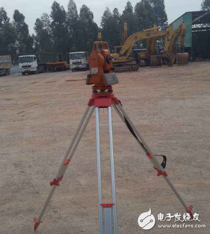
1 Place the Southern Total Station instrument on the test site, centering and leveling.
Place the instrument on the test site, centering and leveling. Place the instrument on the test site, centering and leveling.
2 Press the total station power button to turn it on. The screen shows a vertical angle of zero.
Press the power button to turn it on. The screen shows a vertical angle of zero.
3 Turn the telescope, the screen displays V, HR, and enter the angle measurement interface.
Rotate the telescope, the screen displays V, HR, enter the angle measurement interface. Rotate the telescope, the screen displays V, HR, enter the angle measurement interface.
4Press the MENU button on the panel to display the menu 1/2.
5 Press F1 data acquisition, and the screen displays to select a file.
6 Press F1 to input the file name, and then press the number key on the panel to display the letters and numbers represented by the key at the bottom of the screen, corresponding to F1, F2, F3, F4. After completing the file name input, press F4 back. Car, screen return data collection 1/2 menu
7 Press F1 to input the measurement station. The screen displays the name of the point, the code, and the input interface of the instrument.
8 Press F1 to input, enter the point name in turn, press the F3 station after the instrument is high, and the screen enters the measurement site interface.
9 Press F3 coordinates, the screen enters the measurement site coordinates N, E, Z input interface.
10 Press F1 to input the corresponding coordinate values. Press F4 to return to the screen and the screen returns to the 7th step.
11Press F4 to record, the screen shows the record? [Yes] [No], press F4 to select [Yes], and the screen returns to the Data Acquisition 1/2 menu.
12Press F2 to input the backsight point. The screen displays the backsight point name, code, and prism high parameter setting status.
Press F1 to input, enter the backsight point name in turn, and the prism height parameters. When finished, press F3 rear view, and the screen enters the backsight point interface.
Press F3 coordinates, the screen enters the backsight point coordinates N, E, input interface.
Press F1 to input the corresponding coordinate values. Press F4 to return to the screen and the screen returns to the 12th step.
Press F4 to measure and the instrument displays [Angle] [Slant Distance] [Coordinates]. Aiming at the rear view prism with a rotating total station.
Press F4 to measure and the instrument displays [Angle] [Slant Distance] [Coordinates]. Aiming at the rear view prism with a rotating total station.
At the F1 angle, the instrument displays the current vertical angle V and azimuth HR.
Press F4 to record and the instrument returns to the Data Acquisition 1/2 menu.
Press F3 to measure, the screen displays the point name of the coordinate point to be obtained, the code, and the prism high input interface.
Press F1 to input, and then enter the point name to be requested, and the prism height parameters. When finished, press F3 to measure and the screen displays [Angle] [Slant Distance] [Coordinates] [Eccentricity]. Turn the total station to the center of the prism to be measured.
Press F1 to input, and then enter the point name to be requested, and the prism height parameters. When finished, press F3 to measure and the screen displays [Angle] [Slant Distance] [Coordinates] [Eccentricity]. Turn the total station to the center of the prism to be measured.
Press the F3 coordinate and the instrument displays the N, E, and Z values ​​of the point to be requested.
Press F4 to record, the total station instrument returns to step 18, input the parameters of the new point to be requested, and press F4 to perform the data acquisition of the new point to be requested.
Lifepo4 Lithium Battery,26650 Battery,3.2V Lifepo4 Lithium-Ion Battery ,26650-3300Mah Battery
Henan Xintaihang Power Source Co.,Ltd , https://www.taihangbattery.com