
The fluxgate current sensor is based on the fluxgate technology and the application of closed-loop control in electronic circuits. The fluxgate sensor has high resolution, wide range of measurement weak magnetic field, reliable, and can directly measure magnetic field. The components are suitable for use in speed motion systems. The following is a detailed introduction to the working principle and structure of the fluxgate current sensor.
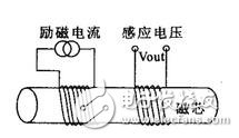
Fluxgate current sensor worksThe working principle of the fluxgate sensor is based on the nonlinear magnetization characteristics of the core material. The sensitive component is a core made of high magnetic permeability and easy-saturated material. There are two windings around the core: one is an excitation coil. The other is the signal coil. Under the magnetization of the alternating excitation signal fl, the magnetic permeability of the iron core undergoes periodic saturation and non-saturation changes, so that the induction coil surrounding the iron core induces a signal reflecting the external magnetic field.
Because the fluxgate sensor uses the high magnetic permeability of the magnetic field in the measured magnetic field under the saturation excitation of the alternating magnetic field, the nonlinear relationship between the magnetic induction and the magnetic field strength is used to measure the weak magnetic field. This physical phenomenon seems to be a "gate" to the measured magnetic field. Through this "gate", the corresponding magnetic flux is modulated and generates an induced electromotive force. This phenomenon is used to measure the magnetic field generated by the current, thereby indirectly achieving the purpose of measuring the current.
Flux gate current sensor schematic
Second, the composition of the fluxgate current sensor
The following figure shows the system configuration of the fluxgate current sensor.
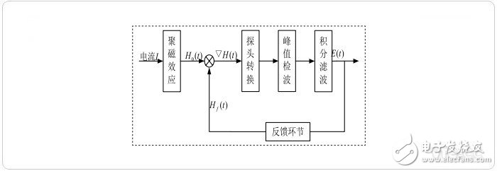
Fluxgate current sensor system block diagram
The system block diagram of the current sensor is shown. The magnetic field generated by the current is modulated by the excitation signal in the fluxgate probe, and a useful voltage signal is generated by the peak detection and integration filter circuit, and then the feedback is made to operate the current sensor in the zero flux state.
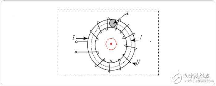
Figure 1: Flux gate winding structure
The following article introduces a single-winding fluxgate that is simple in structure and widely used. As shown in Fig. 1, a coil is wound around the toroidal core, which acts as an excitation winding and as a measuring winding, and the measured current passes through the middle of the magnetic ring.

Figure 2: Common magnetic ring B-H curve
Generally, magnetic materials have the characteristics of an S-shaped curve, which is called a hysteresis loop, as shown in FIG. The hysteresis loop curve is established on the coordinate axis of B-H, and the magnetic material is subjected to a fully magnetized and non-magnetized period, which is illustrated as a core of a typical hysteresis curve. If the curve starts from point a, this point represents the maximum positive magnetization force. The magnetization force to point b is zero, then drops to point c as the maximum negative magnetization force, then the magnetization force at point d is zero, and finally returns to point a of the maximum positive magnetization force, which is the entire magnetic period. The hysteresis loop of the high permeability and low coercivity core is shown in Figure 3.

Figure 3: B-H curve of a high u magnetic ring
When we add a current component to the magnetic loop wire, the magnetic field generated by the current causes the originally symmetrical BH hysteresis loop to change the centerline to a shape as shown in FIG.
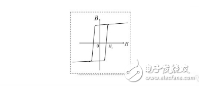
Figure 4: High-U magnetic ring B-H curve with DC added
Assuming that the excitation magnetic field strength is: Hmcosωt, the total magnetic field strength on the fluxgate core can be obtained as:
……1
In the formula:
H 0 - the magnetic field strength of the wire current on the toroidal core;
H m - is the amplitude of the excitation magnetic field strength;
ω - is the excitation field angle frequency.
Then the induced electromotive force in the coil:
……2
In the formula:
N——the number of turns of the winding coil;
S—— is the cross-sectional area of ​​the toroidal core;
uTd - is the differential permeability of the core material.
According to the magnetic saturation characteristics, when H0 = 0, H(t) = Hm cosωt, and the magnetic induction under magnetic saturation is:
...3
Where: Ba is the intercept of the extension line of the saturation curve of the magnetization curve on the B axis. Obviously, B(t) is a flat top wave that is symmetric about the time axis. According to the Fourier series analysis, it only contains odd harmonics. The wave does not contain even harmonics.
When the external magnetic field H0≠0, H(t)= H0+Hm cosωt, the expression of B(t) is:
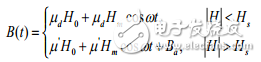
...4
At this time, B(t) becomes an up-and-down asymmetrical flat-top wave. According to the Fourier series analysis, it not only contains odd harmonics but also even harmonics. As can be seen from Equation 2, E(t) and B(t) should contain similar waveform components. Therefore, the magnetic field B0 generated by the external current can be detected based on the upper and lower asymmetry of the amplitude of E(t) in the excitation period. Thereby achieving the purpose of measuring current.
The whole process can be summarized as follows: When the fluxgate type current sensor operates, the excitation coil is loaded with a fixed frequency and a fixed waveform alternating current for excitation, so that the reciprocating magnetization of the magnetic core is saturated. When there is no measured magnetic field generated by the external current, the induced electromotive force outputted by the detecting coil contains only the odd harmonics of the excitation waveform, and the waveform is positive and negative symmetrically. When there is a DC external magnetic field, there is a DC magnetic field in the core.
And exciting the alternating magnetic field, the DC measured magnetic field causes the excitation field to saturate the magnetic core in advance in the first half cycle, and delays the saturation of the magnetic core in the other half cycle. Therefore, the positive and negative half cycles are asymmetrical during the excitation period, so that the amplitude difference occurs in the output voltage curve. This amplitude difference is proportional to the magnetic field generated by the current to be measured, so that the amplitude difference can be used to detect the current passing through the magnetic ring.
Smd Mic,Smd Microphone,Smd Condenser Microphone,Smd Dynamic Microphone
NINGBO SANCO ELECTRONICS CO., LTD. , https://www.sancobuzzer.com