Capacitive loads can affect the stability of the op amp circuit, resulting in a lot of overshoot and ringing. When the situation is severe, it will cause oscillation. How to deal with this "bad" op amp capacitive load?
In fact, there is a lot of information on the basic stability theory, but the following small experience tells you how to avoid the amplifier oscillation with a simple calculation method.

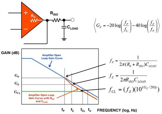
In general, if you use an amplifier to drive a capacitive load (Figure 1, CLOAD), a good rule of thumb is to separate the amplifier from the capacitor with a 50 or 100 ohm resistor (RISO). This additional resistor may prevent the op amp from oscillating.
Figure 1. An amplifier supporting a capacitive load may require a resistor to be connected between the amplifier output and the load capacitor.
However, using 50 or 100 ohm (RISO) resistors does not always work. The question is, "What if CLOAD exceeds the op amp capacitance load recommended in the product manual?"
If you are unable to find any instructions, or if your load capacitance (CLOAD) does exceed the recommended value in the product manual, the answer to the question depends on:
· Amplifier gain bandwidth product (GBWP or fU)
· Open loop output resistance (RO) of the amplifier
· Capacitor load value (CLOAD)
The frequency and gain plots in Figure 1 show the amplifier's open-loop gain curve when RISO and CLOAD are applied to the amplifier output. If you use these three variables, you can calculate the appropriate RISO value.
Here are the rules for determining the RISO value:

(Formula 1)

(Formula 2)
These two rules ensure the stability of the circuit.
An application suitable for this concept is to drive the input to the SAR-ADC. In this case, the signal needs to be stable during the acquisition time (tACQ) of the converter. K in Equation 3 is an ADC time constant multiplier that provides high precision for half LSB. For a 16-bit converter such as the ADS7886, K is equal to 11.78.
(Formula 3)
Let's apply these formulas and calculate them with the following parameters:
· For OPA365
· fU = 50 MHz
· R0 = 30 ohms
· Gain = 1 V/V
· For ADS7886
· tACQ = 300 ns
· CIN = 21 pF
· CLOAD = 390 pF
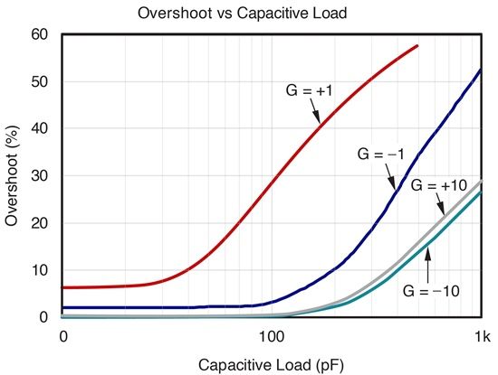
The OPA365 data sheet shows that a load of 100 pF produces a 30% overshoot (Figure 2).

Figure 2. OPA365 overshoot and capacitive load
Equations 1, 2, and 3 can help solve this overshoot problem.
· Equation 1, RISO => 3.33 ohms
· Equation 2, RISO => 30.97 ohms
· Equation 3, RISO ~ 61.96 ohms
Given these three formulas, RISO must be equal to 61.9 ohms (0.1% tolerance).
Some manufacturers include typical performance curves for stability and capacitive loading in their product specifications. They will even be explained in the electrical performance table. Of course, this information is very helpful. However, you can also avoid amplifier oscillations or excessive overshoot by using the calculations used in this article.
Uv Curing Hd Film,Curved Tempered Glass,Plastic Screen Protector,Mobile Film Cuttting Machine
Shenzhen TUOLI Electronic Technology Co., Ltd. , https://www.hydrogelprotectors.com
