
How does the full-bridge power supply DC blocking capacitor suppress the bias?
There is less information on the analysis and calculation of the bridge power supply DC-blocking capacitors on the network. Let's take a brief analysis together.
First, a simple diagram of a simple full-bridge power switch section

When the full bridge power supply does not have a DC blocking capacitor as shown above
Nothing in the world can be absolutely identical. There are no subtle differences between the two leaves in the world. The duty cycle of Q1Q4 and Q2Q3 is also the same.
The full-bridge topology Q1Q4 and Q2Q3 are alternately turned on. Here we assume that the duty cycle of Q1Q4 is slightly larger than that of Q2Q3.
When Q1Q4 is turned on, the primary winding of the transformer is left and right negative. When Q2Q3 is turned on, the primary winding of the transformer is right and left negative, but since the conduction time of Q1Q4 is longer than the conduction time of Q2Q3, magnetic induction The intensity B is a little bit per cycle, and a lot of accumulations eventually lead to saturation of the core, which is very dangerous.
When the full bridge power supply increases the DC blocking capacitor C1 as shown below

As above, we assume that the Q1Q4 duty cycle is greater than the duty cycle of Q2Q3. For DC blocking capacitors, the time from left to right on the DC blocking capacitor is greater than the time from the right to the left. When Q1Q4 is on, the C1 is charged. Q2Q3 When the conduction time is separated, the straight capacitor C1 is discharged, the charging time of the capacitor is inconsistent with the discharging time, and a DC parallax occurs in the voltage on the capacitor.
When Q1Q4 is turned on, the voltage on the Np winding is: the input voltage minus the parametric voltage of the DC blocking capacitor C1; when Q2Q3 is turned on, the voltage on the Np winding is: the input voltage plus the parametric voltage of the DC blocking capacitor C1. When the on-time is short (Q2Q3 pass), the voltage across the Np winding is higher. When the on-time is long (Q1Q4-pass), the voltage across the Np winding is low, and the final volt-second balance.
Of course, when the Q2Q3 duty cycle is greater than the Q1Q4 duty cycle, you can adjust it. You can analyze it yourself.
Calculation of DC blocking capacitor C1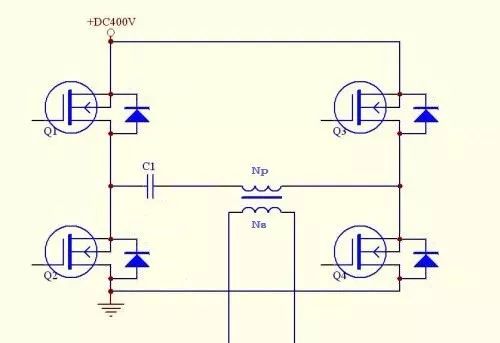
The DC blocking capacitor C1 is in charge and discharge state every cycle. There is always a voltage fluctuation (ripple) on C1. The value of DC blocking capacitor C1 should be moderate. If the capacitor value is too small, the ripple voltage on C1 will be A large difference between the waveform and the square wave on the transformer winding is relatively large. The power supply is not well designed. Assuming that the capacitance value is too large, the dynamic suppression effect of the bias magnet will be poor. According to our experience, we generally make the ripple voltage on C1 about 10% of the input voltage.
The formula for estimating the capacitance of C1 is
CV=it
C: The capacitance of the DC blocking capacitor C1 is the required value here.
V: is the ripple voltage. If the input voltage is 400V, take 10%, 40V.
i: is the average value of the charging or discharging current of the DC blocking capacitor. Since the DC blocking capacitor C1 and the winding Np are on the same path, i is the average current of the primary winding under the maximum load of the power supply (including the transformer transmission current and inductance). Excitation current).
t: charging time or discharge time of the capacitor (ie, the turn-on time of Q1Q4 or the turn-on time of Q2Q3)
Note: This is an estimate of the DC blocking capacitor and is ultimately based on the debug value.
Withstand voltage of DC blocking capacitor C1
The withstand voltage of the DC-blocking capacitor is very low under normal operating conditions. However, if the power supply has a transient abnormality or other conditions are not good, it is recommended to select a higher withstand voltage than the input voltage.
Single-Element Detector,Hortwave Detector Unit,Swir Infrared Detector,Swir Ingaas Unit Detector
Ningbo NaXin Perception Intelligent Technology CO., Ltd. , https://www.nicswir.com