
If you've ever looked for a Texas Instruments device, you've probably seen the tool shown in Figure 1. This product selection tool is powerful enough to help you quickly review hundreds of devices.
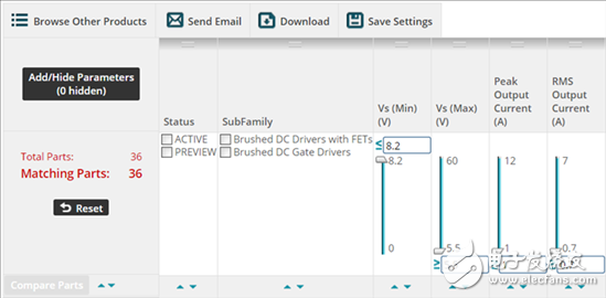
Figure 1: Product Selection Tool
However, as the saying goes, useless input will bring useless output. So understanding the different specifications of the device sought is the key to finding the right device. In our issue of the Motor Drive Forum question and answer, I will mainly talk about the most easily misunderstood motor drive specifications: drive current rating. I will also check the two drive current parameters, peak output current and root mean square (RMS) output current.
The peak output current is the maximum current that the motor driver can deliver without regard to the thermal limits of the device and its package. This limit is usually set by the overcurrent protection (OCP) of the motor drive (Figure 2).
Figure 2: OCP limit (peak output current)
Example of protection limits in the DRV8840 datasheet
When the current drawn is greater than the OCP limit, the driver stage will be turned off. An exception to the peak output current limit is that the motor driver will allow a higher current for a short period of time during the OCP anti-spike timer. The anti-spike timer ensures that the noise of the switch or output capacitor does not trigger the OCP and causes the shutdown.
The waveform in Figure 3 shows a typical OCP event of the motor driver output during a short circuit. The yellow trace is the input signal, the blue trace is the fault output signal, and the pink trace is the current flowing through the output stage. At the beginning, the current rises rapidly. After a brief overshoot (this overshoot does not affect the output stage), the current is limited to approximately 9A by an analog current limit. After approximately 2.5 μs, the OCP anti-spike timer expires and the current temporarily stays at the 9 A analog current limit, which exceeds the OCP limit. On this device, the OCP level is approximately 3A. At this point, the output stage is disabled, the current drops to a value of zero, and a fault occurs.

Figure 3: OCP event
The RMS output current is the maximum RMS (or DC) current that the motor driver can support under fixed conditions. Typically, these conditions include operating at a nominal voltage, an ambient temperature of 25 ° C, and using a standard JEDEC-compliant printed circuit board (PCB). This limit is usually set by the overtemperature protection of the motor drive. Once the device exceeds the overtemperature limit, the driver stage will shut down. This ensures that the device does not operate outside of its safe working area.

Figure 4: Over temperature limits for the DRV8840 data sheet
Other resources:
Learn more about hot topics on the TI.com/thermal website.
Read this "Understanding Motor Driver Current Ratings" application report to learn more about the output current rating and the protection mode used by TI motor drivers.
Search for questions and answers in the TI E2ETM motor-driven community or ask the motor application team.
Due to electrical equipment installed in heating control switchboard the distribution of electrical energy maybe controlled automatically. Sensors installed in the facility, give information about ambient temperature, temperature of the object and temperature of the inner medium of the object.
Then, depending on the information received and set working modes, automatic Control Cabinet will switch on or switch off the heating, increase or decrease necessary temperature. Thus, the use of heating switchboard ensures proper and economical energy management, as well as rapid response and prevention of emergency situations.
Performed main tasks are following:
switching of high-power power supply and heating sections for the roof and gutter systems, water pipes and large diameter tanks, parts of the object in the open air, electrical systems, floor heating in the buildings or in the open areas;
Protection against electrocution;
Protection against short-circuit.
Functionality of the heating systems control cabinet
Functions of heating control system may differ depending on the requirements and specifications of the customer. Main functions are:
the possibility to switch control modes (manual or automatic);
maintain the set temperature of the heated object;
operating mode control;
Heating equipment protection from overheating, over current(overload), short circuit protection;
a complete and safe shutdown of heating equipment from the power supply in case of accidents.
Thermal Oil Control Panel,Thermal Oil Control Box, Fuel Oil Control Panel, Marine Fuel Oil Control Console
Nantong Double Star Automation Equipment Co., Ltd. , https://www.nt-doublestar.com