
Network interface layer protocol
The network interface layer in TCP / IP corresponds to the physical layer and the data link layer in the OSI model. It is the bottom layer of TCP / IP, but it is usually divided into a physical layer and a data link layer when describing the TCP / IP model .
1. The main task of the physical layer is to determine the characteristics of the transmission media interface. These characteristics include four aspects:
1) Mechanical characteristics. Explain the shape and size of the connector used in the interface, the number and arrangement of pins, the position of fixing and locking, etc.
2) Electrical characteristics. Specifies the level characteristics of the pin, that is, how much the voltage range, and how to represent 1 and 0.
3) Functional characteristics. Specifies the physical meaning represented by each level appearing on the pin
4) Procedure characteristics. Specifies the sequence of events that occur in the realization of a function, that is, the temporal relationship of events.
2. Services provided by the physical layer to the data link layer
1) Physical connection, providing a physical channel for the link layer to transmit bit streams
2) Physical Service Data Unit (PSDU), for serial transmission, the transmission unit is 1 bit, for parallel transmission, the transmission unit is 8 bits or more
3) Including fault events and providing quality parameters. Although the physical layer does not provide error correction services, it can set the data transmission rate and detect the data error rate.
3. A channel is a path for transmitting signals, including transmission media and related intermediate communication equipment. The main parameters of the channel are: the passband f of the signal, the available time t, the signal-to-noise ratio S / N, the limited bandwidth (baud rate) and the maximum transmission rate (channel capacity, expressed in bit rate), etc.
4. Multiplexing technology refers to the method of simultaneously transmitting multiple limited bandwidths on the same transmission medium, which is called multiplexing. The multiplexing type can be divided into frequency division multiplexing, wavelength division multiplexing, time division multiplexing and code division multiplexing.
5. There are two major systems of digital carrier, T-standard (used in North America, Japan) and E-standard (used in China, Europe, and South America). Both of these standard systems use time division multiplexing technology.
6. Data transmission synchronization methods include asynchronous transmission and synchronous transmission (divided into character-oriented synchronization method and bit-oriented synchronization method)
7. The switching methods are divided into circuit switching, message switching, and packet switching also becoming packet switching (there are two methods: datagram and virtual circuit).
8. The transmission media are: coaxial cable (coax, which is the media commonly used to form Ethernet in the past, but it is rarely used now, divided into 50 Euro, 75 Euro (mainly used for TV cable), 90 Euro three types), double Twisted pair (TP is divided into shielded twisted pair STP and unshielded twisted pair UTP), optical cable (single mode and multi mode), wireless transmission (infrared transmission, radio frequency transmission, communication satellite transmission)
9. Examples of physical layer standards: RS-232-C, RS-449
Data link control and its protocol
1. Basic concepts
The main functions implemented by the data link layer include link management, framing and frame synchronization, error control, flow control, and providing services for the network layer.
1) Link: refers to a passive point-to-point physical line segment, without any other switching nodes in the middle, and the communication channel between the two end points is formed by multiple links in series
2) Data link: refers to the transmission path from the data sending point to the data receiving point. The concept of the data link includes the physical link and the hardware and software that implement the control data transmission procedures
3) Data link control procedure: refers to the control method used to enable data to reach the receiving point quickly, correctly, and efficiently. Therefore, it can be understood that the link is an unreliable physical transmission line, and the data link refers to a logical link that can be reliably transmitted. Through multiplexing technology, there can be multiple data links on a link.
2. Functions realized by the data link:
1) Provide services for the network layer, including non-confirmed and connectionless services, confirmed and connected services, and confirmed and connected services.
2) Link management, including the establishment, maintenance and release of data links
3) Framing and frame synchronization, the main framing methods are: character counting method, the first and last character delimitation method with character padding, the first and last mark delimitation method with bit filling, physical layer coding violation law.
4) Error control, including bit error and frame loss in the frame
5) Flow control is mainly to control the rate of data sent by the sender to ensure that the receiver can process the data sent by the sender in time. The current method is mainly based on the feedback mechanism.
6) Transparent transmission of data
7) Addressing. For the case of multi-point connection, there must be a corresponding addressing mechanism to ensure that each frame can be sent to the correct target station, and the receiver is required to know which site the sender is.
3. Error detection and correction, two strategies for handling errors are the use of error correction codes and the use of error detection codes
Error correction codes are: parity check code, Hamming code. Error detection code: checksum, CRC
4. Basic data link layer protocol (simplex working mode)
1) The unconstrained simplex protocol is an ideal communication protocol, including the sending program and receiving program.
2) Protocols such as simple stop are mainly to solve the flow control, but they are still based on the ideal situation of no noise.
3) The simplex protocol with noisy channels is closer to the actual communication system, and it is necessary to solve the processing of error frames, including timeout retransmission.
5. Sliding window protocol (full-duplex working mode)
In the full-duplex working mode, there are simultaneous transmission and reception of data frames and response frames in the dual transmission of the communication, so after receiving a data frame, the receiver can temporarily delay the response frame to be sent in order to append the response frame to the next The data frame to be sent, this technology is called confirmation piggyback / load answering technology. The sliding window protocol includes a one-bit sliding window protocol, a backward n-frame protocol, and a selective retransmission protocol.
6. The formal methods for developing and describing laundry are: finite state machine, formal language, Petri net, process algebra
7. Commonly used data link layer protocols
The data link layer has many types of protocols, which can be divided into character-oriented link layer protocols and bit-oriented link layer protocols. With the development of computer communications, the character-oriented link control procedures gradually revealed their weaknesses, and the bit-oriented procedures that appeared later are more suitable for computer communications, and these bit-oriented procedures are similar.
1) Character-oriented link layer protocol. Such as ISO's basic transmission control regulations and its extension IS1746, IBM's binary synchronous communication procedures BSC, DEC's digital data communication message protocol DDCMP, point-to-point protocol PPP.
2) Bit-oriented link layer protocol. Such as IBM's synchronous data link control protocol SDLC, ANSI improved SDLC advanced data communication control protocol ADCCP, ISO modified SDLC proposed data link control HDLC, CCITT modified HDLC proposed link access procedure LAP as X.25 network Part of the interface standard was later changed to LAPB.
8. The application scope of the advanced data link layer control procedures HDLC includes computer-to-computer communication, computer-to-terminal communication, and terminal-to-terminal communication. In the HDLC protocol, a most basic concept is a data station. The so-called data station is a terminal and a computer responsible for sending and receiving data frames. HDLC defines three types of data stations: a master station, a slave station, and a combined station. In the HDLC protocol, two configurations suitable for links are also defined, namely unbalanced configuration and balanced configuration.
9. Internet data link layer protocol
At present, there are generally two methods for users to access the Internet, one is dedicated line access, that is, router to router, and the other is to connect to the router or access server through dial-up Internet access, no matter which method is used to transfer data. At all times, you must use the data link layer protocol. The widely used protocols in the Internet are SLIP, PPP and PPoE.
1) Serial line IP (SLIP, proposed in 1984) has many disadvantages and is difficult to popularize.
2) Point-to-point protocol PPP, link establishment process: create PPP link-"user authentication-" call network layer protocol.
3) PPPoE (full name is Ethernet-based point-to-point communication protocol)
At present, there are fewer and fewer users accessing the Internet through Modem dial-up, so the future development of the PPP protocol is not optimistic, and the data link layer protocol is to meet more and more broadband Internet access equipment (ie ADSL, wireless, cable ) And the newly established standard for communication between faster and faster networks, it is based on two widely accepted standards, namely Ethernet and PPP dial-up protocol. PPPoE can be understood as implementing PPP protocol through Ethernet.
Instruction Manual
1. Features
Clock display, 10 sets of adjustable timed power control, randomized power control, manual switch and optional DST setup.
2. First time charging
This Timer contains a rechargeable battery. It is normal that the new/old model runs out of battery if it wasn`t being charged for a long period of time. In this case, the screen will not turn on.
To charge : simply plug the timer to a power outlet. The charging time should take at least 15 minutes.
If the screen doesn`t light up or displays garbled characters, simply reboot the system by pressing the [RESET" button.
3. Set clock

Hold [CLOCK" button and [WEEK" button to adjust week.
Hold [CLOCK" button and [HOUR" button to adjust hour.
Hold [CLOCK" button and [MINUTE" button to adjust minute.
Hold [CLOCK" button and [TIMER" button to select 12 hour/24 hour display.
Hold [CLOCK" button and [ON/AUTO/OFF" button to enable/disable DST (daylight-saving-time).
4. Set timer
Press [TIMER" button, select and set timer. Setting rotation : 1on, 1off, 2on, 2off, ...... , 10on, 10off.
Press [HOUR" button to set hour for timer.
Press [MIN" button to set minute for timer.
Press [WEEK" button to set weekday for timer. Multiple weekdays can be selected. ex: if selected [MO", the timer will only apply on every Monday; if selected [ MO, WE, FR", the timer will apply on every Monday, Wednesday and Friday.
Press [RES/RCL" button to cancel the selected on or off timer. The screen will show "-- -- : -- --" , the timer is canceled.
Press [RES/RCL" button again to reactivate the timer.

When timers are set, press [CLOCK" to quit timer setting and return to clock.
5. Random function

Press [RANDOM" button to activate random function, press again to cancel function.
System only runs random function when [AUTO" is on.
Random function will automatically start the timer from 2 to 32 minutes after the setting.
ex : if timer 1on was set to 19:30 with the random function on, the timer will activate randomly between 19:33 to 20:03.
if timer 1off was set to 23:00 with the random function on, the timer will activate randomly between 23:02 to 23:32.
To avoid overlapping, make sure to leave a minimum of 31 minutes gap between different sets of timer.
6. Manual control
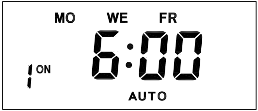
Displayed features:
ON : socket turns on.
OFF : socket turns off.
AUTO : socket turns on/off automatically via timer.
Manual ON setting
Press [ON/AUTO/OFF" button to switch from [AUTO" to [ON".
This mode allows socket of the device to power up. Power indicator will light up.
Manual OFF setting
Press [ON/AUTO/OFF" button to switch from [AUTO" to [OFF".
This mode turns socket of the device off. Power indicators will turn off.
7. Electrical parameters
Operating voltage : 230VAC
Battery : NiMh 1.2V
Power consumption : < 0.9W
Response time : 1 minute
Power output : 230VAC/16A/3680W
Q&A
Q: Why won`t my timer turn on?
A: It`s out of battery, you can charge the timer by plugging onto any power outlet. Charge the device for at least 15 minutes. Then press [RESET " button to reset the device.
Q: Can I set seconds of the timer?
A: No, the smallest time unit is minute.
Q: Does my timer keeps old settings without being plugged onto a power outlet?
A: Yes, the timer has an internal battery, it allows the timer to save settings without a power outlet.
Q: Is the battery rechargeable?
A: Yes, the battery is rechargeable. We recommend to charge it for 4 hours so the battery is fully charged.
Q: Does the timer needs internet connection?
A: The timer does not need internet.
Q: Does the screen have back light function?
A: It doesn`t support back light.
digital timer, digital timer socket, electronic timer socket, timer socket
NINGBO COWELL ELECTRONICS & TECHNOLOGY CO., LTD , https://www.cowellsocket.com