
In the case of no external controller (such as a PLC), there are three ways to directly operate the inverter: 1 the keys on the operation panel; 2 the components connected to the operation terminals (such as buttons and potentiometers); 3 the composite operation (such as the operation panel To set the frequency, operate the button connected to the terminal block for start/stop control). For easy operation and full use of the inverter, PLC can also be used to control the inverter.
The PLC controls the frequency changer to have three basic ways: 1 controls by the switch quantity; 2 controls by the analog quantity; 3 controls by the RS485 communication way.
PLC controls the hardware connection of the inverter in a switch mode
Inverter has a lot of switch terminals, such as forward rotation, reverse rotation and multi-speed control terminals, etc. When PLC is not used, as long as these terminals are connected to the switch, the inverter can be forward rotation, reverse rotation and multi-speed control. . When using the PLC to control the inverter, if the PLC is to control the inverter in a switch mode, it is necessary to connect the PLC's digital output terminal with the inverter's digital input terminal. In order to detect certain states of the inverter, you can also The digital output terminals of the inverter are connected to the digital input terminals of the PLC.
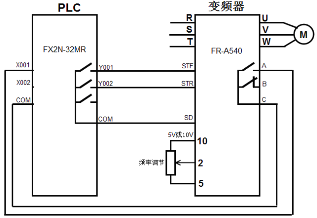
The hardware connection of the PLC controlled by the switch mode is shown in the figure below. When the PLC program internal operation makes the Y001 terminal internal hard contact closed, equivalent to the inverter STF terminal external switch is closed, STF terminal input is ON, the inverter starts the motor forward rotation, adjust the 10,2,5 terminal connected potentiometer The input voltage of terminal 2 can be changed, thereby changing the frequency of the frequency converter output power and changing the speed of the motor. If an internal fault occurs in the inverter, the internal contacts between the A and C terminals are closed, which corresponds to the external switch of the X001 terminal of the PLC being closed and the X001 terminal input being ON.
PLC controls the hardware connection of the inverter in analog mode
The inverter has some analog input terminals for voltage and current. Changing the voltage or current input value of these terminals can change the rotation speed of the motor. If these terminals are connected to the analog output terminals of the PLC, the PLC can be used to control the inverter to adjust the motor. The speed of rotation. The analog quantity is a kind of continuous change quantity, can make the rotational speed of the electric motor change continuously with the control function of the analog quantity (continuously variable speed).
The PLC controls the hardware connection of the inverter in analog mode as shown in the figure below. Since the Mitsubishi FX2N-32MR PLC has no analog output function, it needs to connect it to an analog output module (such as FX2N-4DA) and then to the analog output module. The output terminals are connected to the analog input terminals of the frequency converter. When the STF terminal external switch of the inverter is closed, the terminal input is ON, the inverter starts the motor forward rotation, and the digital data generated when the PLC internal program is running is sent to the analog output module (DA module) through the connection cable. The voltage (analog quantity) converted into the range of 0-5V or 0-10V is sent to the inverter terminals 2, 5 to control the frequency of the inverter output power, and then to control the rotation speed of the motor. If the DA module outputs to the inverter 2, 5 When the voltage of the terminal changes, the output frequency of the inverter will also change and the motor speed will change.

When the PLC is controlling the analog input terminal of the inverter in analog mode, the digital input terminal of the inverter can also be controlled by the switch mode.
PLC controls the hardware connection of the inverter with RS485 communication
When the PLC controls the inverter by the switch mode, it needs to occupy more output terminals to connect the input terminals of the corresponding functions of the inverter, so that the inverter can be controlled in forward rotation, reverse rotation, and stop; the PLC controls the frequency converter in analog mode. When you need to use the DA module to frequency control the frequency converter. If the PLC uses RS485 communication to control the inverter, only one RS485 communication cable (contains five core wires) is used to directly send various control and frequency modulation commands to the inverter. The inverter is sent by the PLC through the RS485 communication cable. The instruction can perform the corresponding function control.
RS485 communication is a communication method widely used in industrial control at present, and has strong anti-interference ability, and its communication distance can reach several tens of meters up to 1000 meters. Using RS485 communication can not only connect two devices to communicate, but also connect multiple devices (up to 32 devices in parallel) to form a distributed system to communicate with each other.
1. RS485 communication port of the inverter
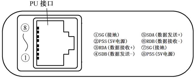
Mitsubishi FR500 series inverter has a PU port for connecting the operation panel. This interface can be used as RS485 communication port. When communicating with other equipment using RS485 mode, it is necessary to pull out the operation panel plug (RJ45 plug) from the PU port. Plug one end of the RS485 communication cable into the PU port and connect the other end of the communication cable to the PLC or other device. Mitsubishi FR500 series inverter PU port outline and pin function description as shown below.
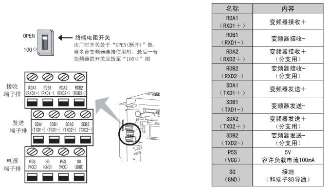
Mitsubishi FR500 series inverter has only one RS485 communication port (PU port), panel operation and RS485 communication can not be carried out at the same time. Mitsubishi FR700 series inverter, in addition to a PU interface, is also equipped with a separate RS485 communication port (terminal block), Dedicated to RS485 communication. The appearance of the RS485 communication port of Mitsubishi FR700 series inverter and the description of each pin function are as shown in the following figure. Each function terminal of the communication port has two, one is connected to one RS485 communication device, and the other is connected to the next RS485 communication device. If there is no next device, the terminating resistor switch should be set to the "100Ω" side.
2. RS485 communication port of PLC
Mitsubishi FX PLC generally does not have an RS485 communication port. To communicate with the inverter via RS485, an FX2N-485BD communication board must be installed in the PLC. The outline and terminals of the 485BD communication board are shown in Figure (a) below, and the installation method of the communication board is shown in Figure (b) below.
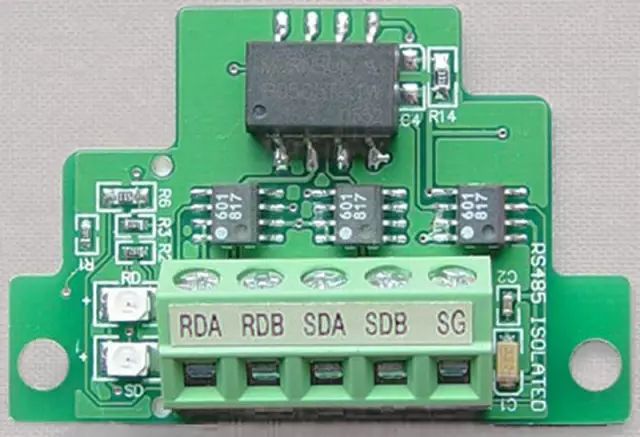
(a) Shape
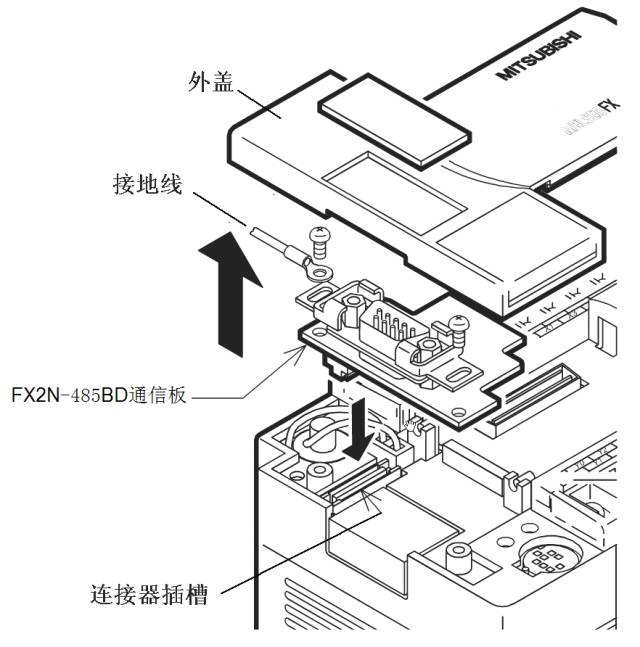
(b) Installation method
3. RS485 communication connection between inverter and PLC
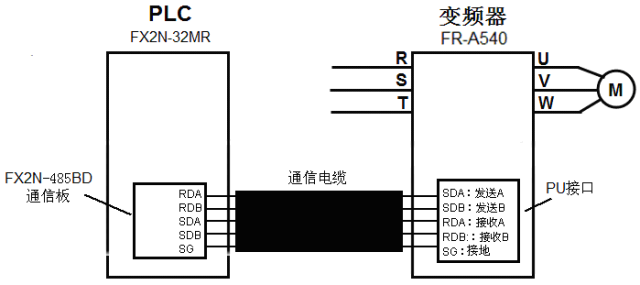
(1) RS485 communication connection between single inverter and PLC
The RS485 communication connection between a single inverter and the PLC is shown in the following figure. When the two are connected, the sending terminal (+\-) of one device should be connected to the receiving terminal (+\-) of the other device, respectively. The terminals (+\-) should be connected to the sending terminal (+\-) of the other device.
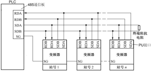
(2) RS485 communication connection between multiple inverters and PLC
The RS485 communication connection between multiple inverters and the PLC is shown in the figure below. It can realize the operation of one PLC to control multiple inverters.
PLC control inverter drive motor forward and reverse circuit, program and parameter settings
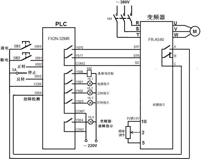
1.PLC and inverter hardware connection circuit diagram
The circuit diagram of the PLC controlling the inverter's driving motor forward and reverse according to the switching mode is shown in the figure below.
2. Parameter setting of the inverter
When using PLC to control the inverter, you need to set related parameters of the inverter. For details, see the table below.
| parameter name | Parameter number | Settings |
| acceleration time | Pr.7 | 5s |
| deceleration time | Pr.8 | 3s |
| Acceleration and deceleration frequency | Pr.20 | 50Hz |
| Base frequency | Pr.3 | 50Hz |
| Maximum frequency | Pr.1 | 50Hz |
| Lower limit frequency | Pr.2 | 0Hz |
| Operating mode | Pr.79 | 2 |
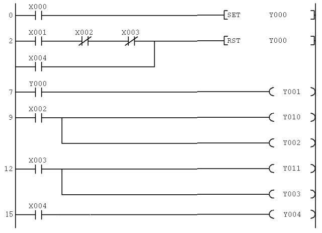
3. Write PLC control program
After the relevant parameters of the inverter are set, use the programming software to write the corresponding PLC control program and download it to the PLC. PLC control inverter drive motor forward and reverse PLC program as shown below.
The PLC controls the circuit, program and parameter setting of the inverter drive motor multi-speed operation
Inverter can be continuous speed control, can also be divided into speed, FR-500 series inverter RH (high speed), RM (medium-speed) and RL (low speed) three control terminals, through the combination of the three terminals input, 7 speed control can be achieved. If the output terminals of the PLC are connected to these terminals of the inverter, the inverter can be controlled by the PLC to drive the multi-speed operation of the motor.
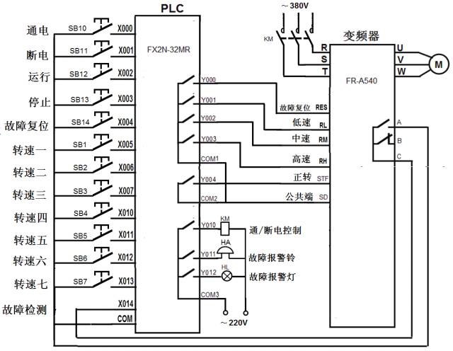
1.PLC and inverter hardware connection circuit diagram
The circuit diagram of the PLC to control the inverter's multi-speed operation with the switch mode is shown in the figure below.
2. Parameter setting of the inverter
When using the PLC to perform multi-speed control of the inverter, it is necessary to set relevant parameters of the inverter. The parameters can be divided into basic operating parameters and multi-speed parameters, as shown in the following table.
| classification | parameter name | Parameter number | Setting value |
| Basic operating parameters | Torque boost | Pr.0 | 5% |
| Maximum frequency | Pr.1 | 50Hz | |
| Lower limit frequency | Pr.2 | 5Hz | |
| Base frequency | Pr.3 | 50Hz | |
| acceleration time | Pr.7 | 5s | |
| deceleration time | Pr.8 | 4s | |
| Acceleration and deceleration frequency | Pr.20 | 50Hz | |
| Operating mode | Pr.79 | 2 | |
| Multi-speed parameters | One speed (when RH is ON) | Pr.4 | 15 Hz |
| Rotation speed 2 (when RM is ON) | Pr.5 | 20 Hz | |
| Speed ​​3 (When RL is ON) | Pr.6 | 50 Hz | |
| Rotation Speed ​​4 (When RM and RL are ON) | Pr.24 | 40 Hz | |
| Speed ​​5 (L when RH and RL are ON) | Pr.25 | 30 Hz | |
| Rotation speed six (when RH and RM are ON) | Pr.26 | 25 Hz | |
| Rotation speed 7 (When RH, RM, and RL are all ON) | Pr.27 | 10 Hz |
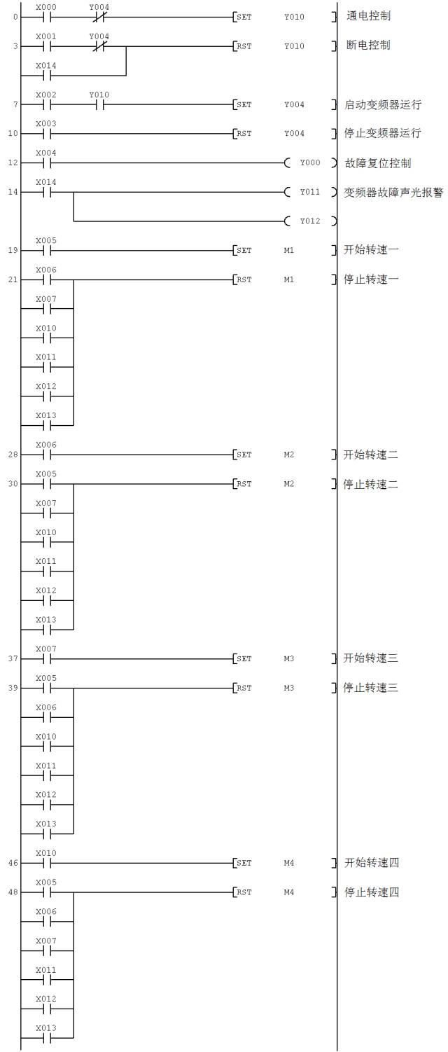
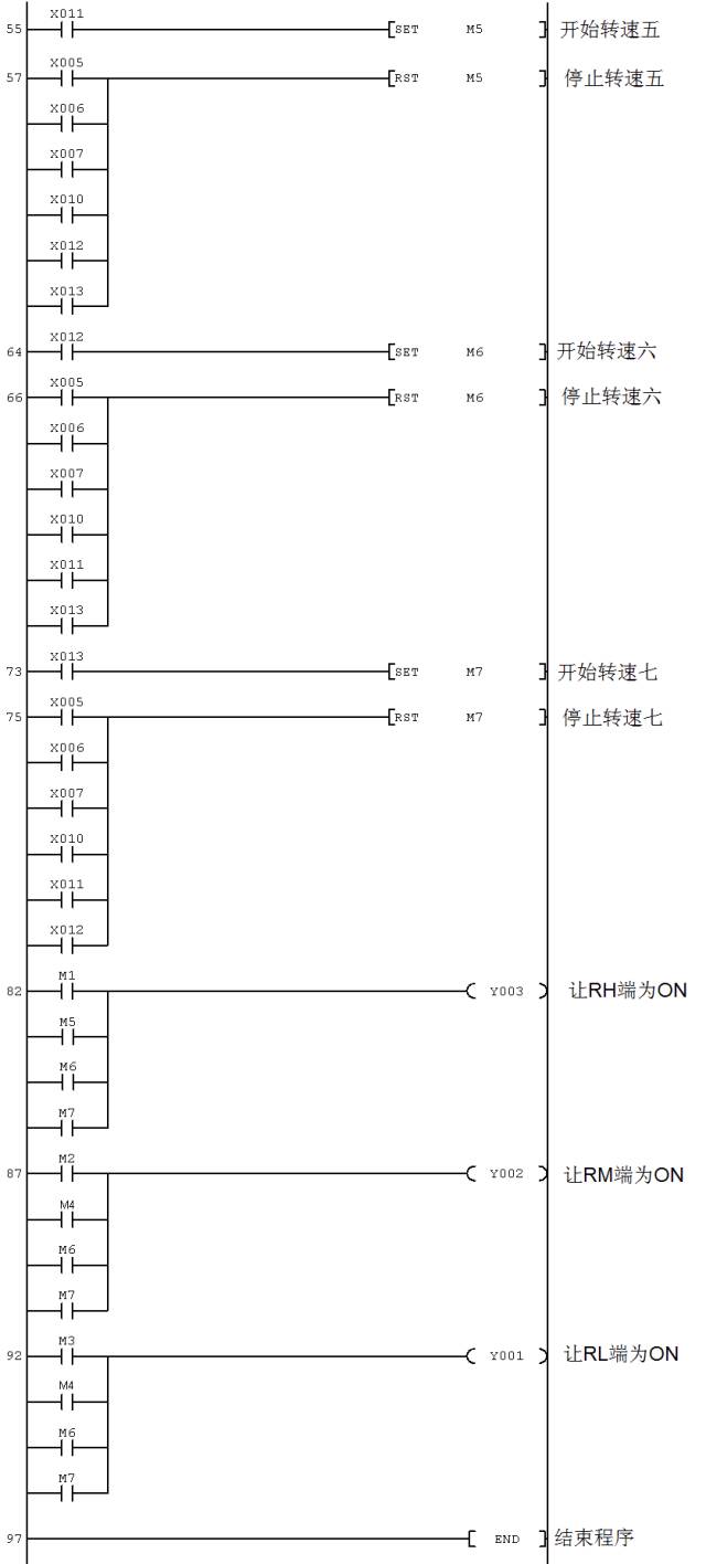
3. Write PLC control program
The following PLC program is used to control the inverter's multi-speed rotation motor running in PLC mode.
Diesel Generator Power Range,Single Phase Diesel Generator,Mobile Type Diesel Generator,Standby Power Diesel Generator
Shanghai Kosta Electric Co., Ltd. , https://www.ksdpower.com