
Power system planning and design, there are many contents, designing all aspects of the power system, roughly divided into the following parts, only one part.
First, the main network planning and design1) Grid and solution
The grid and solution are the core of power system planning and design. The grid can be divided into nine grid structures through simplified analysis.
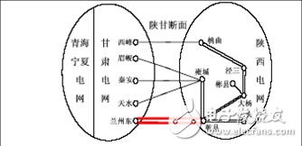
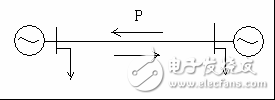
A system with a balance of capacity is connected to a larger part of the interconnected system
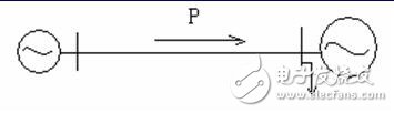
For such a power grid structure, the occurrence of a power angle stabilization accident should be avoided. The reason is that the heavy load tie line fault jumps, causing other tie lines to be overloaded, the power output of the send end is blocked, and the frequency of the send end system is increased, and if the receiving end is sufficiently large, the frequency reduction may be relatively small. However, it will cause the oscillation of the power angle and power of the generator group at both ends of the tie line, which will cause stable damage in severe cases.
In order to prevent the occurrence of a stable accident, the load-receiving measures should be taken at the receiving end, the cutting machine should be cut at the sending end or the power generation should be reduced, or the tie-line disengagement strategy should be adopted to disassemble part of the power supply to the receiving end, or it will be partially affected. The end load is unpacked to the sending end to calm the oscillation.
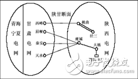
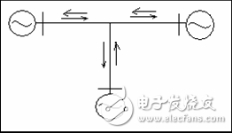
The part of the interconnected system with power shortage gets power from the large capacity part
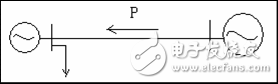
Such a structure should avoid accidents with stable power angle and voltage stability.
The cause is that in the part of the active power shortage, the frequency is drastically reduced, and the power angle of the receiving end system and the transmitting end system is out of synchronization. It is also possible that the receiving end system voltage collapses due to a serious shortage of reactive power in the receiving end system. At this point, the tie line should be quickly cut off and the unimportant load removed in the receiving grid. Therefore, it is necessary to install a low-frequency load-reduction and low-voltage load-reduction device, and install a generator set self-starting device when conditions permit.
Two power equivalent systems are connected via a strong tie line
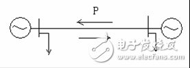
This kind of structure has the characteristics of high stable operation level and strong grid structure, and it is not easy to cause stable damage accidents. However, in severe interlock failures, tie line overload or power angle out of synchronization may occur. In this case, strategies such as reducing the output of the generator and removing a certain load should be adopted.
The two parts of the connected system are connected by weak links
This type of structure is generally in the early stages of interconnected systems. This kind of structure is prone to dynamic stability loss. That is, the system produces negative or weak damping. Oscillation of long processes does not decay and divergence.
In this case, the construction of the grid structure should be strengthened as soon as possible, the impedance of the tie line should be reduced, and an automatic device that increases the positive damping of the system, such as PSS, should be added, and the load shedding measures should be taken to reduce the transmission power of the tie line.
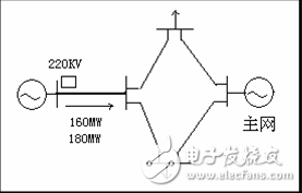
More complicated three-machine wiring
The operational characteristics of this type of structure are that the system tie lines interact with each other. When a heavy-duty tie line is disconnected due to a fault, it may cause a dangerous change in the way the other tie line operates.
In such cases, a strategy should be taken to prevent a chain reaction from being broken after a tie line is disconnected.
Chain wiring
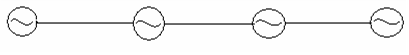
In this type of wiring structure, in general, some of the tie lines always transmit power in one direction, and the power transmission lines on other tie lines vary with different time periods. Within a day and night, some of the power systems connected together are sometimes lacking in power and sometimes more than enough.
Therefore, the degree of possible accident damage and the interaction of the tie lines during the accident will also change accordingly. Its characteristics are: the operation mode of the system has a great influence on the contact line at the time of failure, and the power angle stability, voltage stability and frequency stability may occur, and the accident may be enlarged due to dangerous overload of individual links in the wiring.
Radioactive structure
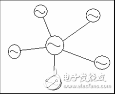
In this configuration, the central system is often much larger than other systems (adjustable), and the central system can send power or receive power. When the power is deficient, it can cut off part of the load, and in the power balance, it can reduce the power generation, and it can ensure that no overload occurs on any radial type contact line. If the subsystem is out of step with the main system, the tie line can be unblocked to prevent further expansion of the accident. Such wiring is not prone to large-scale power outages.
Ring wiring
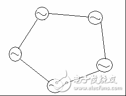
This type of wiring is characterized by a variety of operating modes. If any link is disconnected, it will not only cause the change in the transmission power of each link in the ring, but also its direction. The overall mode of operation of the entire ring is determined by its “hazardous sectionâ€, which increases the power hazard of the other section. Therefore, this kind of wiring structure has gradually been eliminated. If necessary, add equipment to the device.
Multi-loop system
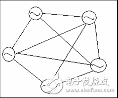
This kind of wiring structure is the final ideal structure of the power grid. This structure can maintain the stability of the system under a variety of faults.
The understanding of the grid mentioned above is the basis for the formulation of the power system plan.
The designation of the scheme in the actual project must consider both technical and economical.
Technically, nothing more than engineering meets load requirements, electrical calculations must meet conditions, and have certain long-term adaptability. Higher requirements are aesthetics of the grid; economics means that investment costs are as low as possible.
Comprehensive technical and economical, and then get a recommendation.
Consideration of the vertical structure of the power grid
It is the strength and weakness of each level of the grid 500kV-220kV-110kV-10kV.
The general principle is: the highest voltage level grid should be strong; the second level grid has certain support capacity for the upper level grid; the medium voltage distribution network close to the user should be strong.
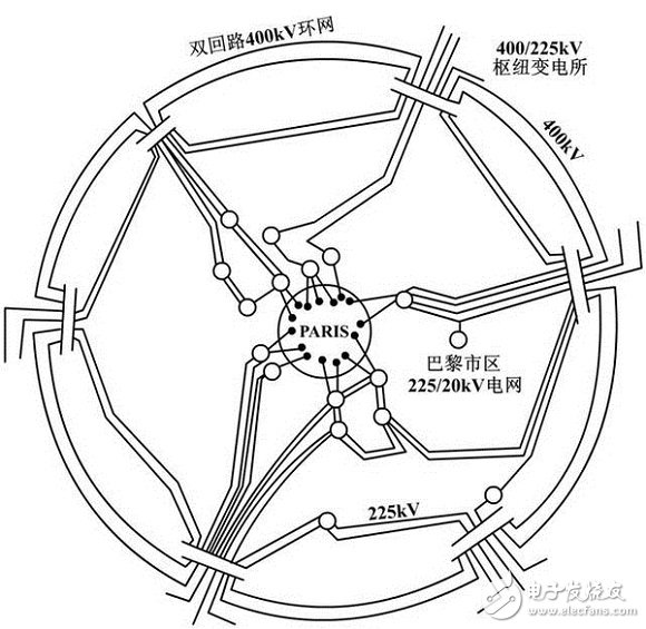
Paris power grid, ideal for strong-weak-strong power grids.
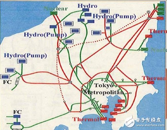
The Tokyo power grid, power distribution and load distribution characteristics determine the large power flow in the Tokyo power grid.
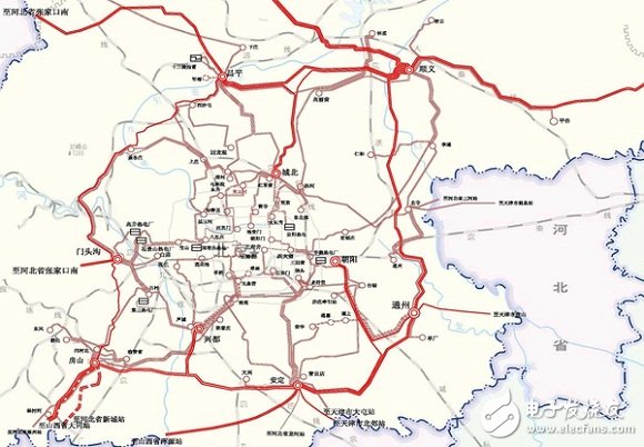
Beijing Power Grid, domineering strong-strong-strong-strong power grid, 500 kV is a double loop network, 220 kV, 110 kV is mainly double-chain, and the 10 kV target is gridded.
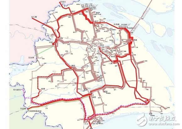
Shanghai Power Grid, strong-sub-strong-sub-strong-strong grid, 500 kV is mainly based on double-ring network, but Jingan can not meet the requirements of N-1-1 or N-2 (so the last power outage has a great impact ); 220 kV network is the hub and terminal station mode, and the intermediate station is reduced as much as possible.
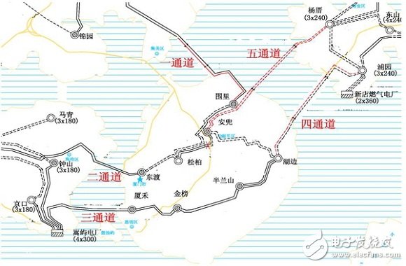
In Xiamen Power Grid, the target grid is a strong-weak-strong structure, 220 kV is a multi-feedback, weakening 110 kV, and 10 kV gridding.
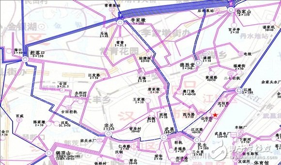
Wuhan Hankou Power Grid, the strong-weak-strong-secondary power grid in the main urban area, the external power supply is 500 kV double loop network and 220 kV main power plant, 220 kV is double feedback, and 110 kV is double return chain The 10 kV target is gridded.
2) Electrical calculation analysis
This part is divided into two parts, some of which are rough hand calculations, or estimates, depending on experience, and some are computer software calculations, such as PSSE, BPA, EMTP.
About hand calculation
First of all, you should be familiar with various power system formulas, such as zero sequence, conversion in different cases, positive calculation of short circuit impedance, etc. These are professional basics.
Then we must be familiar with each plan, that is, how to choose the size of this substation, how to connect this line, how to build this power plant, you need some general judgment, which requires some simple calculations.
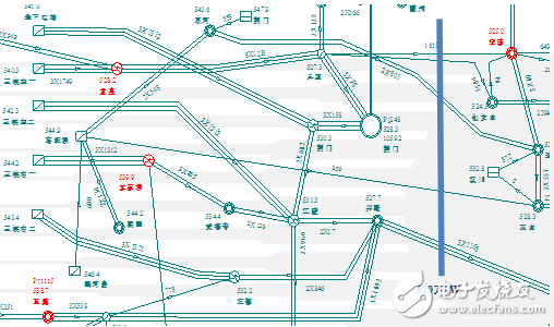
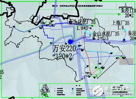
For example, power supply capabilities, such as the trend section margin (blue line in the figure), such as the static stability limit, can be roughly calculated.
Finally, there are hand calculations that require experience, such as stable discriminant algorithms, etc. These are some of the more advanced things.
The basis of these hand calculations is very useful for quickly qualitatively determining a power system problem, or for diagnosing grid problems in a country overseas.
About electrical software calculations, mainly include conventional power flow calculation, short circuit calculation, stability calculation, over voltage calculation, reactive power calculation, etc.
The calculation of the power flow is mainly to select different calculation methods, such as Feng Da & Feng Xiao & Big & Dry, to check for some weak links, such as whether there is a line overload problem (including the N-1 situation) and so on.
Short-circuit calculation is also to check some points with high short-circuit levels. Is there any phenomenon that exceeds the standard? Generally speaking, the short-circuit level and power supply capacity are contradictory. How to balance and optimize the power grid structure is a key.
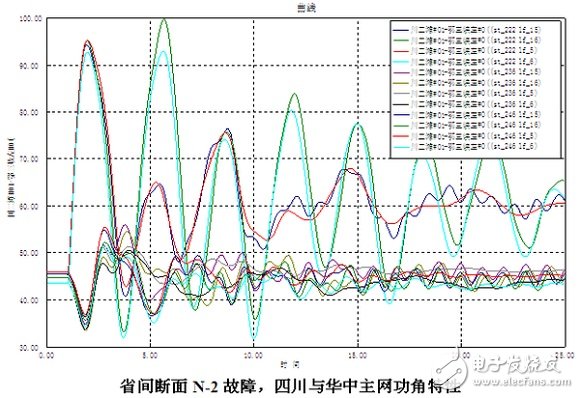
For stable calculations, the static stability limit, the transient stability limit (described in the previous essay), and then the stability level under various fault modes, such as a single instant, such as Sanyong, such as a faultless disconnection, Wait, if there are stability problems, it is necessary to calculate the analysis in detail, such as the stability control strategy, load shedding scheme, etc. This part requires some experience.
Overvoltage calculation, high voltage level, generally 500kV, will require calculation of internal overvoltage, EMTP to calculate, also more professional. There are several main concerns about internal overvoltage. One is whether the various overvoltage levels are up to standard, one is reactive configuration, the configuration scheme of the high voltage shunt reactor, one is whether to install the closing resistor, and the other is the neutral point. The configuration scheme of the small reactance is also described in detail in the previous essay.
The reactive power calculation is based on the principle of hierarchical partitioning and calculation of reactive power balance. These have calculation steps, and then use software to simulate the voltage fluctuation level under different switching modes according to the calculation result.
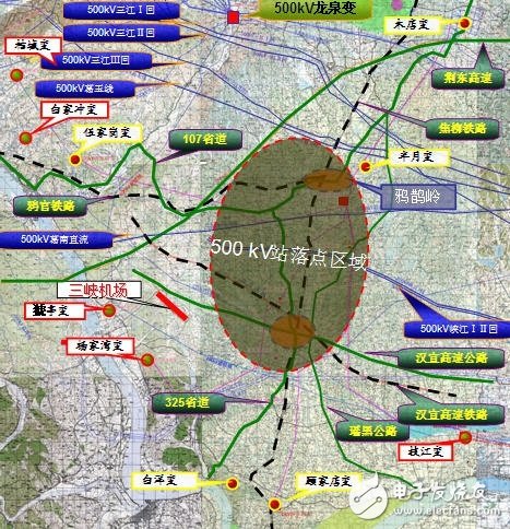
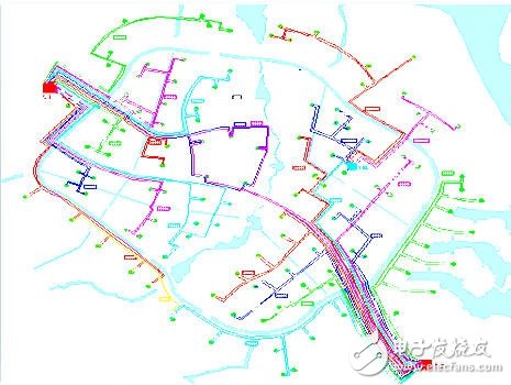
3) Site selection
Power plants, substations, and lines all require site selection (path), which is a key point for the planning and design phase.
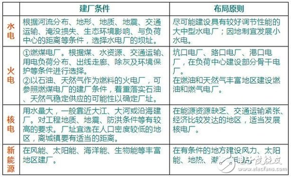
Power plant site selection
Substation site selection
1. Close to the load center
It is necessary to find out the status and role of this substation in advance. Choose a location that is closer to the center of the load.
2, make the regional power supply layout reasonable
The regional power and substation are not concentrated on one side so that the power supply layout is dispersed.
3, high and low pressure sides of the line is convenient
Not only must the delivery wire be able to get in and out, but also the crossover of the delivery line is small and the corner is small.
4. The topography, landform and land area of ​​the area should meet the requirements of recent construction and development.
The spirit of saving land, not occupying or occupying farmland should be implemented, and various arrangements should be adopted to adapt to the topography and topography.
5. The site cannot be flooded and washed by flash floods, and the geological conditions should be suitable.
6. When determining the site, consider the interaction between it and neighboring facilities.
7, convenient transportation
It is necessary to consider not only the transportation of large equipment during construction, but also the transportation convenience during operation and maintenance.
8, with reliable water source, convenient drainage
9. Convenient construction conditions
When selecting a place, it is also necessary to consider the problems of construction water use, construction site, labor, and convenient sources of construction materials.
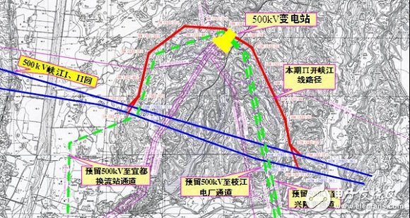
Line path
[Topography, Geology, Natural Conditions] Line selection personnel must conduct detailed investigations on the topography, geology, and natural economic conditions of the area through which the line passes, and fully negotiate with relevant units along the line to select the most appropriate route.
[Short path] The path of the selected line should be as short as possible, the line corner should be less, and the angle of the spit angle should be small, and the special cross-over should be less. Hydrological and geological conditions are better.
[Convenient maintenance and construction] It should be considered that the line has good maintenance and construction conditions, and the traffic along the line should be convenient. It should be as close as possible to the railway, highway or navigable river.
[Does not affect communication] It should be kept at a sufficient distance from the main communication line, airport, radio station and other facilities.
[Does not affect production and life] The line should try to avoid residential areas, factory areas and other areas where buildings and structures need to be demolished, and should not cause difficulties in transportation and machine farming.
[Geological conditions are appropriate] should avoid as far as possible unfavorable geological areas, mining areas that may collapse, swamp areas, forest areas, green areas, orchards, heavy ice areas, pollution areas, explosion critical areas, strong earthquake areas and rural fixed yards, etc. area.
[Uniform planning of the plant and the exit line] The exit corridors of power plants and substations should be considered in accordance with the system development plan, and loops or multi-circuit towers should be adopted in crowded areas.
[Evacuation, avoiding explosion, avoiding collision] Distribution lines should try to avoid factories, warehouses, storage tanks, etc. with explosives, flammable materials and combustibles, and avoid being easily covered by vehicles.
[Coordination with town planning] should be coordinated with town planning.
In the line selection method, it is divided into the line on the map and the line on the field. The planner conducts the primary selection on the topographic map of one of 50,000 to one hundred thousand according to the above-mentioned line selection principle, and then selects according to the map. The path is on-site.
It is assumed that the urban power grid planning work mainly involves two voltage levels of 110kV and 10kV (the planning of the 380V sub-area is not introduced here). Planning work consists of the following basic steps:
1) Data collection, survey and entry 2) Analysis and evaluation of the status quo network 3) Determination of the main technical principles of the plan
4) Load and load distribution prediction 5) Capacity and position determination of 10kV distribution transformers 6) Optimization of 110kV substation
Planning and power supply range calculation 7) 10kV distribution network planning 8) 10kV planning distribution network reliability calculation 9) 110kV distribution network planning 10) reactive power optimization plan 11) Investment estimation and economic benefit analysis
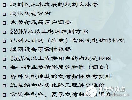
1. [Data collection, investigation and entry]
Urban power grid planning needs to be based on a large amount of basic data, including historical data on urban load development, detailed land use planning and urban development planning data for future urban development.

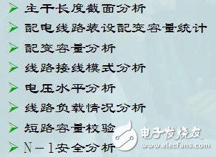
2. [Status Network Analysis and Evaluation]
Using the various analysis tools provided in the system, the current network analysis is completed and the weak links in the system are discovered.
It mainly analyzes and evaluates five aspects: distribution network power supply, distribution network equipment and structure, distribution network operation, technical and economic indicators, equipment maintenance and management.
3. [Determining the main technical principles of planning]
Refer to the “Guidelines for Urban Power Network Planning and Design†and the technical guidelines of the provincial and municipal power companies to elaborate technical principles.
The technical principles should include the following main contents:

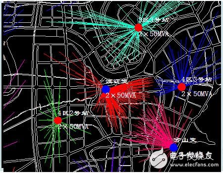
Example: Transformer capacity and number of substations in a province
The final size of the 110kV substation is 3 main transformers.
Intermediate planning year 110kV substation is configured according to 50MVA & TImes; 2 or 63MVA & TImes; 2
The final size of the 110kV substation for the long-term target year is 50MVA & TImes; 3 or 63MVA & TImes; 3 configuration
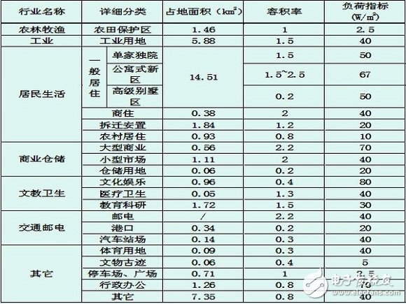
4. [Load and load distribution prediction]
This is one of the most critical tasks in the overall planning effort. The aim is to determine as accurately as possible the load and load distribution for each planned year in the future.
The general principle is based on the land use planning of cities or development zones, based on the prediction of spatial load distribution, using a variety of load forecasting methods for load and load distribution prediction.
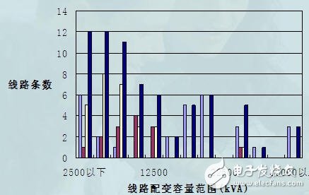
5. [10kV distribution transformer capacity and position determination]
According to the prediction results of the load distribution in the planning area, according to the determined series of distribution capacity, the principle of “small capacity, dense point, short radius†should be adopted, and the capacity and position of each 10kV distribution transformer should be determined by the partitioning method. .
Examples are as follows:
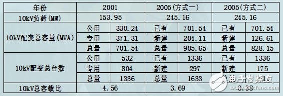
6. [110kV Substation Optimization Planning and Calculation of Power Supply Range]
The purpose is to determine the capacity and location of the 110kV substation. The purpose of the power supply range calculation is to classify all 10kV distribution transformers in the planned area into different 110kV substations according to the power supply relationship. Among them, it is necessary to consider the economics of power supply, but also consider the limitation of the power supply radius.
The capacity of the substation and the number of transformers at this stage are very important and need to be compared and determined.
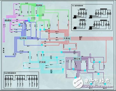
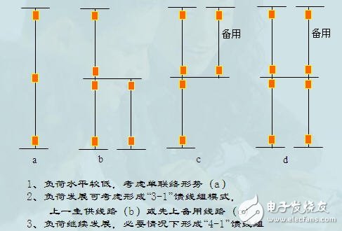
7, [10kV distribution network planning]
According to the calculation results of the power supply range of the 110kV substation, the 10kV distribution network is partitioned according to the power supply range, and the 10kV distribution network is planned according to the partition.
According to the reliability requirements and the main wiring mode adopted, consider the setting of the 10kV tie line between different 110kV substations, and the contact situation of different busbars in the same station.
The planning scheme must meet various system constraints (such as short-circuit capacity limitation, voltage level limit, line overload limit, and N-1 safety guidelines).
The vision planning grid is not built on a completely new area, but is gradually developed to the target grid based on the current load and the current line. Therefore, the vision grid should have strong adaptability and flexibility. When new developments occur in urban development, it can be more flexibly developed into other power supply modes.
Therefore, the transition of the network mode and the network solution should be discussed.
8, [10kV planning distribution network reliability calculation]
Based on the impact of line and switch failures on the system, the planning software will calculate the reliability indicators for each line and the entire 10kV distribution network.
9, [110kV and 220kV power supply network planning]
Similar to 10kV, the channel corridor is more considered.
10, [reactive power planning]
According to the planning results of the 10kV distribution network and the 110kV power system, the reactive power supply planning is completed.
Through calculation, according to the requirements of the guideline, the configuration suggestion of the reactive power device can be given, and the change of the network power flow distribution under the corresponding mode can be calculated, thereby obtaining the improvement of the voltage and the line loss.
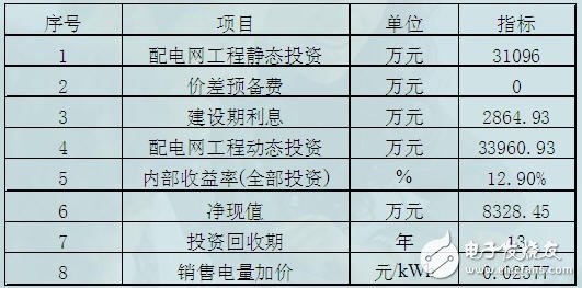
11. [Investment Estimation and Economic Benefit Analysis]
According to the transformation and new network equipment in the planning area, the investment is estimated based on the unit equipment cost. On this basis, it analyzes the economic indicators such as repayment pressure and investment return, and makes clear decision-making opinions for the operation and management of electric power enterprises.
2 In 1 Laptop
Do you know the difference of Yoga Laptop and 2 in 1 laptop? No. 1 is yoga notebook with 360 flip rotating absolutely; No.2 is laptop yoga slim is just like normal Education Laptop-connecting screen with keyboard, but 2 in 1 laptop tablet with pen is separately, you can use the monitor part as a window tablet. In one word, every intel yoga laptop have all the features and function of tablet 2 in 1 laptop except separated screen and keyboard. From the cost, windows yoga laptop is much higher than 2 in 1 type., cause usually former with more complicated craft and quality.
What other products you mainly produce? It`s education laptop, Gaming Laptop, engineering laptop, Android Tablet, Mini PC and All In One PC. You can see more than 5 different designs on each series, believe always have right one meet your special application or your clients demands. Therefore, what you need to do is just to get all the requirement details from your clients, then share the complete information with us, then we can provide the most suitable situation.
Of course, you can also call or email or send inquiry of what you need, thus can get value information much quickly.
2 In 1 Laptop,2 In 1 Laptop Sale,2 In 1 Laptop Tablet With Pen,Tablet 2 In 1 Laptop,2 In 1 Laptop Deals
Henan Shuyi Electronics Co., Ltd. , https://www.shuyielectronictech.com