
A few days ago, the switching power supply at the bottom of the bed was changed to be adjustable. In fact, there is a lack of adjustable power supply to DIY.
This switching power supply is 12V 29A, can be changed to the highest 16V27A adjustable, but adjusted to 16v that the main change is hard, I did not call when I fine-tuned to 15V, then 15V is just right for internal use of common TL494 The interference is as small as 3842 and can almost be ignored. If the difficulty is difficult, everyone in the forum can DIY
The TL494 is powered by an external power supply. It can work if it is not connected. The tl494 operating voltage changes and there may be parameter changes. 
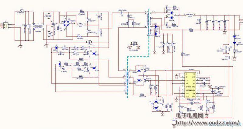
This is a modified adjustable power supply with good stability.
Pick the 47K, 5.6K resistors and connect the 514 pins 15 and 2 to the potentiometer.
UTC TL494, if there is a recommendation from TI or motorcycle
Omron relay, the best with 12V
494 external power supply negative pole connected to the main transformer 494 ground 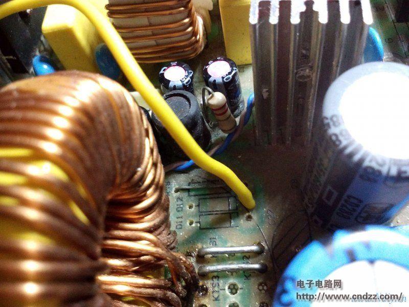
The positive pole is connected to the diode 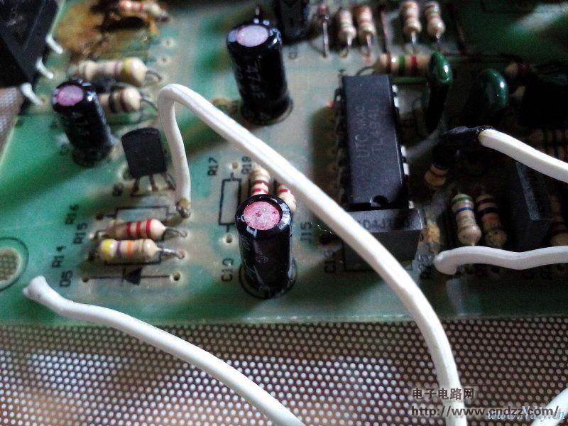
Find the 13 and 14 feet of TL494 (the circuit is directly shorted together), find the resistance to the 15 feet (47K), pick up the end of the 13 and 14 feet, the resistor is connected to the potentiometer boom, and the potentiometer is connected at one end. 13, 14 feet, the other end of the ground to form a flow. Find the 13 and 14 feet of the TL494 (the circuit is directly shorted together), find the resistance to the 2 feet (5.6K), pick up the end of the 13 and 14 feet, the resistor is connected to the potentiometer boom, the potentiometer end Connect the 13 and 14 feet, and the other end is grounded to form a voltage regulator. 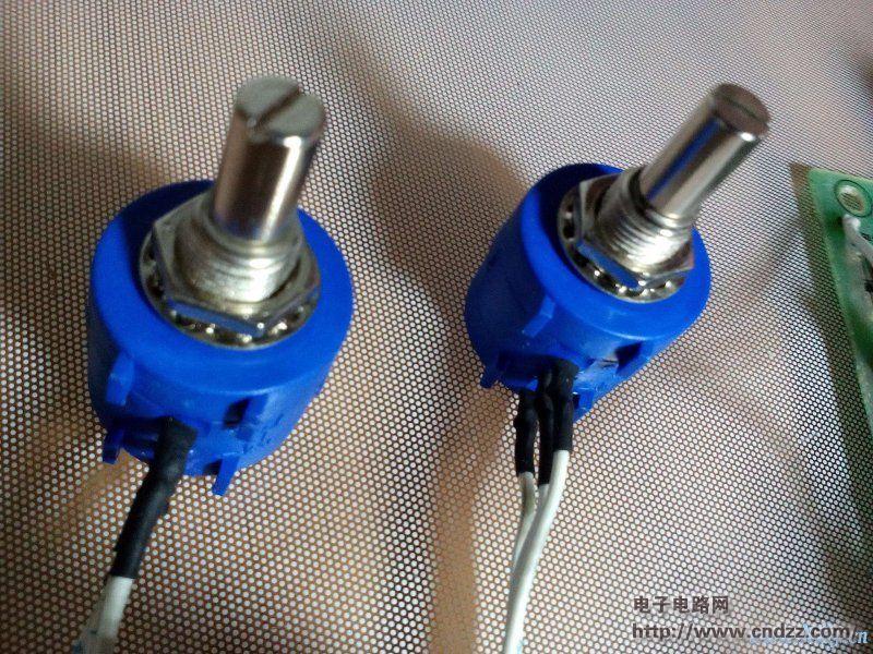
Come to a potentiometer close-up 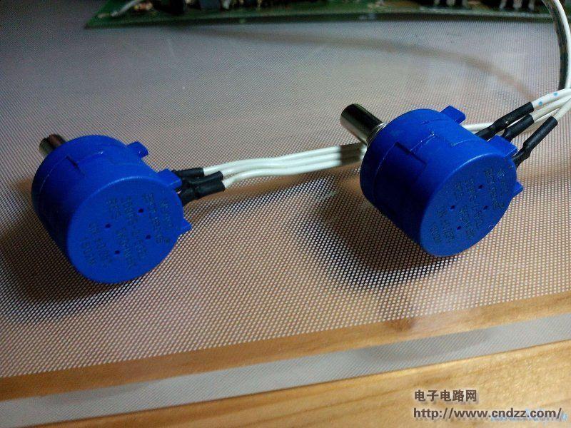
10 treasure potentiometer with 5 yuan on X Bao, good quality 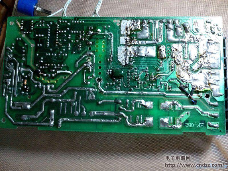
The back can't bear to look straight... 30W electric iron is not strong 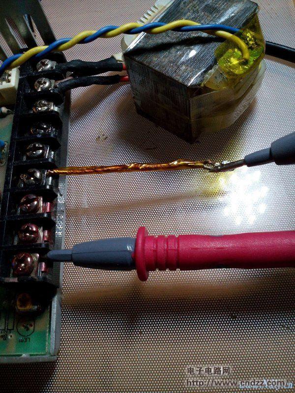
With a piece of copper wire as the load, the voltage is adjusted to 5V, the 15V is not dare, the line is fast. 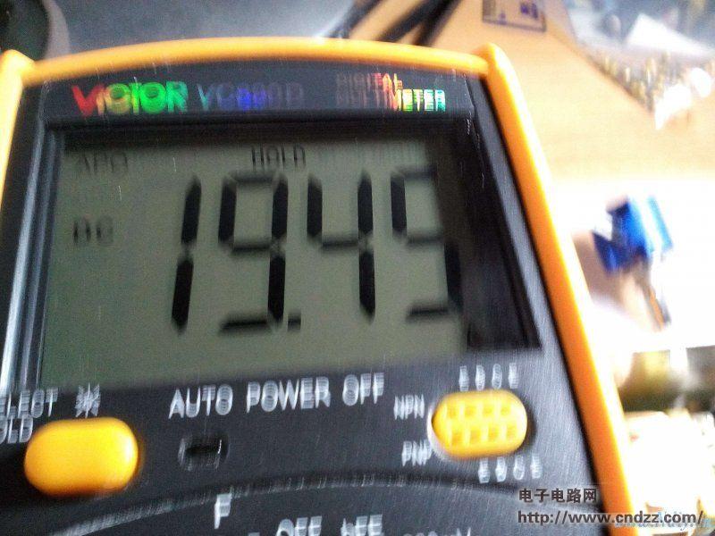
The current is 19.5A, which is enough 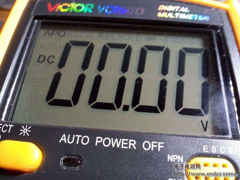
Disconnect the power relay and turn it off. The voltage is 0V. 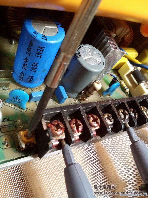
Fine-tuning, adjust the appropriate voltage here and the main transformer is not called. 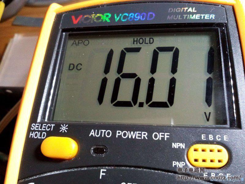
My fine tuning here is 16V, but the main transformer is called awesome. 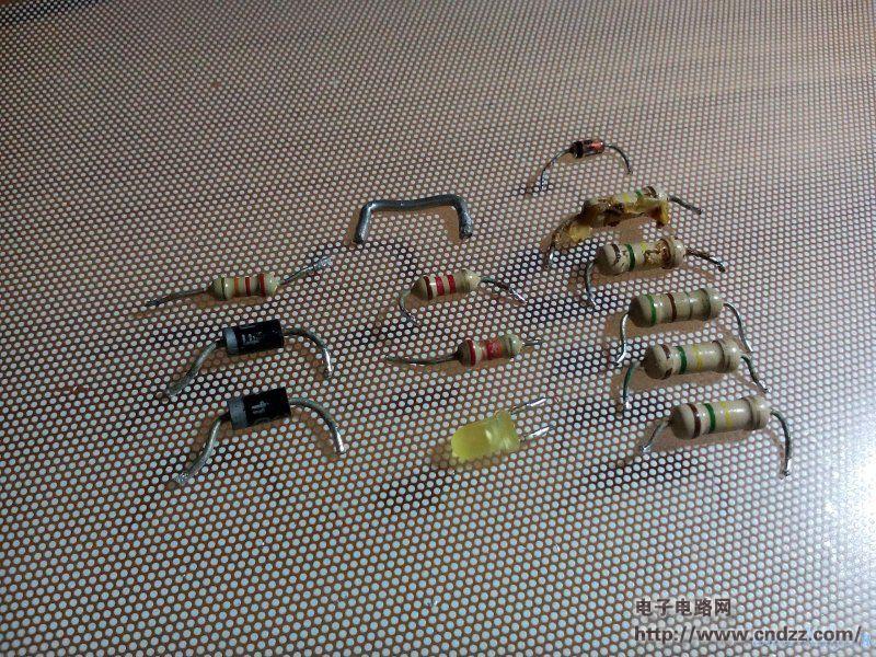
This is the component that needs to be removed this time. 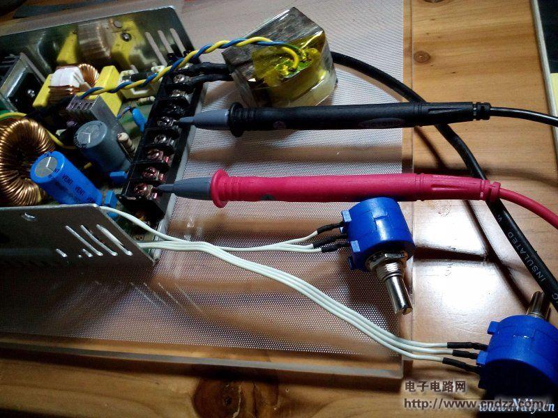
After a few days, the voltmeter ammeter has been further improved.
---Detailed picture change adjustable - pay attention to look carefully!
This is the reference circuit diagram 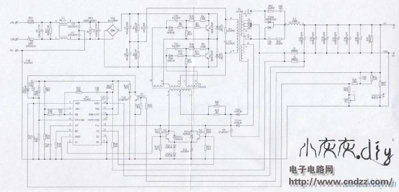
------- Remove the start resistor 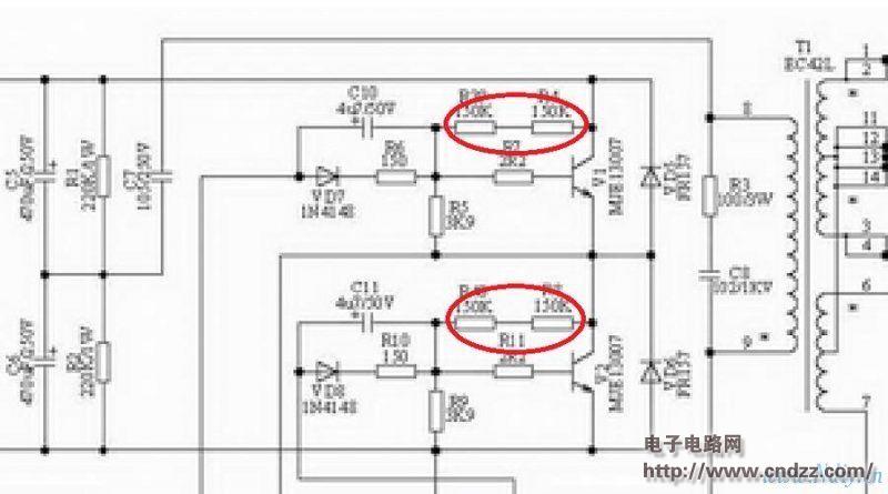
Find the c-pole of the power transistor (usually the middle leg) in the power supply and you will see that there is a diode connected to the resistor.
This resistor is typically a startup resistor that is connected directly or indirectly to the b-pole of the transistor.
Some places are a resistor, and some are connected in series with two resistors to share power consumption and voltage drop.
Corresponding module to inside.
Does the amount of resistance under the amount removed does not match? This resistance is typically 300k, if there are two, it is 150k.
After the power is removed, the module can't be started.
--------Remove the original power supply circuit of TL494 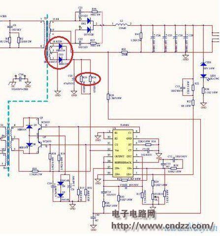
After the startup circuit is removed, the original power supply circuit is useless. If it is not removed, it can work. However, the working voltage of tl494 changes, and there may be parameter changes.
The original power supply circuit generally has a higher operating voltage to ensure smooth start and reliable control, and varies with load.
The resistors and diodes in the ring need to be removed.
Wires need to be shorted to remove the resistor.
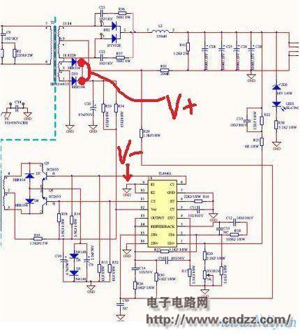
--------- Power the TL494 with a separate power supply.
The positive pole of the external power supply is connected to the position of the original power supply to remove the diode.
The negative pole of the power supply is connected to GND, preferably near TL494.
It is recommended that the external power supply be 12V or 15V, and the power supply is of course DC. 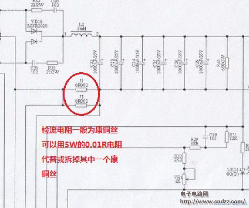
------ Change the current detection resistor.
If the flow detection can be changed or not, use a high-power cement resistor to ensure a low temperature rise and reduce temperature drift.
A cement resistor of 0.01 R is generally used.
The position of the constantan wire is between the output ground and the output reactance. Generally, there is a lot of solder and the copper foil area is large, and the power of the soldering iron is small and it is not easy to disassemble.
The current-sense resistor should be farther away from the rectifier
------Change the output to be adjustable. Change the voltage to be adjustable.
Find the 13 and 14 feet of TL494 (the circuit is directly shorted together), find the resistance to the 15 feet (47K), pick up the end of the 13 and 14 feet, the resistor is connected to the potentiometer boom, and the potentiometer is connected at one end. 13, 14 feet, the other end of the ground to form a flow. Find the 13 and 14 feet of the TL494 (the circuit is directly shorted together), find the resistance to the 2 feet (5.6K), pick up the end of the 13 and 14 feet, the resistor is connected to the potentiometer boom, the potentiometer end Connect the 13 and 14 feet, and the other end is grounded to form the voltage regulation. That is, by changing the potential of the 15 feet to regulate the flow, by changing the potential of the 2 feet to regulate the pressure.
Grounded under the main transformer, connected to the 7th foot of the TL494. 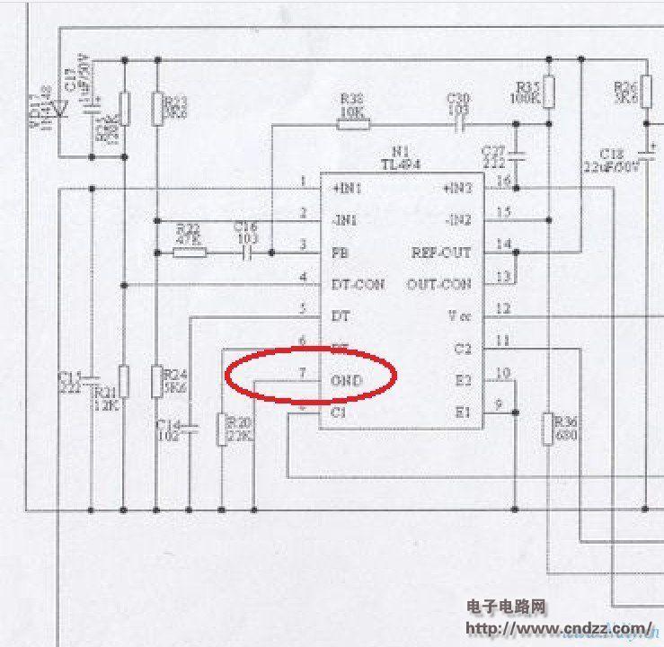
In the red circle, as far as the potentiometer is selected, it is about 5k-10k.
The resistance is too low. The tl494 has a large heat and a large error.
The resistance is too large to adjust the nonlinearity, and the high voltage or large current cannot be fine-tuned.
Potentiometers are recommended to use multiple turns, 10 laps is not bad. It is also possible to use two single-turn potentiometers
--- Increase the output protection of the switch.
Because the TL494 is replaced by an independent power supply, the capacitor at the high voltage is very powerful.
When the output is light, the tl494 is turned off at a low voltage, and there is still a large amount of charge on the high voltage capacitor.
Because the TL494 control is lost, the power supply will work in a self-excited state and the output will be out of control.
Then a device is needed to take over control when the TL494 loses power.
Since this device must be passive, the normally closed contact of the relay is used.
When tl494 has power, let the relay also get electricity, the relay pulls in, and the control is handed over.
When tl494 loses power, the relay is also de-energized or loses power early, the relay is released, and the normally closed contact grabs control. 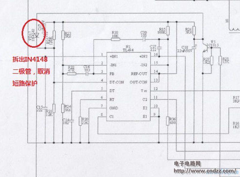
It is recommended that the relay should not be placed too close to the transformer, otherwise the relay will not be fully engaged and the AC sound will be louder.
---Cancel short circuit protection
Remove the diode next to the triode (A1015) to eliminate the short circuit protection. Otherwise, the regulated voltage is lower than 9V. If the short circuit protection determines that the power supply is shorted, the power output will be turned off.
If you don't have this in your switching power supply, ignore this step.
------- Change the output range.
Calculate the resistance of the replacement resistor, the measured resistance * measured current / expected current. For example: resistance = 47k * 5.32 / 10 = 25.004k
The expected current is the output current you need, which can be increased slightly on the basis of the original module, not more than 20%.
This can be ignored 
---------- Increase the voltage.
Eat the redundancy of the original voltage to increase the output voltage. 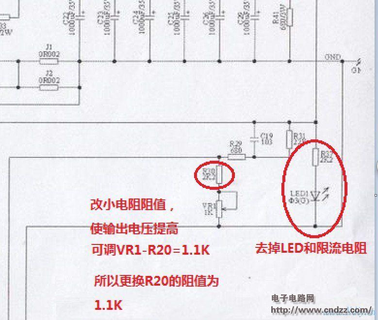
Then replace the capacitor with higher withstand voltage. If the output voltage is smaller than the original, it will not need to be replaced. Pay attention to the polarity when replacing it!
It is recommended to have a tile of 104 at the output there.
Finally, we must carefully check the resistance of the removed components, do not take the wrong position, the direct ignore of the veteran 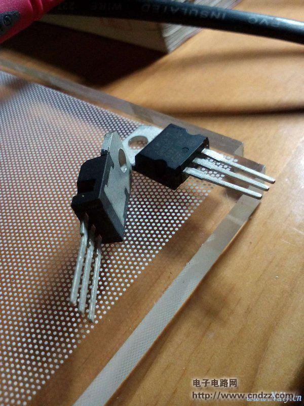
This power supply adjusts the voltage of a certain value. After a few hours, the voltage drift is not big. The stability is much better than that of the 317. As for the LM723, I have not tried to install the LM723.
I bought the 317 before, I want to take time to make an adjustment, but after changing this power supply, it is estimated that this 317 will be broken into the cold. 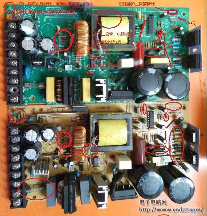
In order to let everyone know how to change, I found a picture, and I have to change the circle. 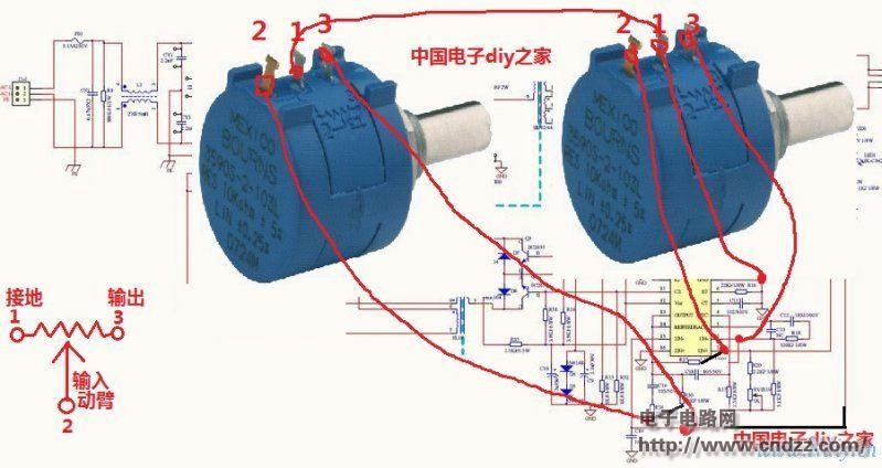
Below is the potentiometer wiring diagram
Final summary:
1. Pick 5.6K and change from 5.6K to 3.9K. Connect the 5--10K potentiometer. ;
2. Remove the starting resistor (two 150K resistors are connected in series to form a self-excited loop). The original function is to connect the B and C poles of the switch tube to form a self-excited oscillation to provide the starting voltage to the power supply.
3. Remove IN4148 at the same time (the purpose is to cancel the short circuit protection).
4. Connect the external power supply (12--17V) to the 494 power supply and connect the negative pole of the power supply to the nearby negative street.
5. The power supply of the external switching power supply is preferably connected to the input voltage terminal of the switching power supply, so that the startup and shutdown of the external power supply can be synchronized with the main power supply.
6, if you need to change the flow, pick up 47K, connect the potentiometer. If it is required to adjust the precise point, it is necessary to change the output current detection of the constantan wire from two parallels to the series. Or change to a high power resistor of 0.01 ohms. 7. Increase the output protection of the switchgear. When the drive transformer drives the transistor B, it is connected to the relay, and the relay takes power from the fan.
The success rate is 100% successful as long as it is correct.
It is not recommended to change the switching power supply of UC3842 to be adjustable. The radio frequency interference of 3842 is much larger than that of 494, and it is troublesome to supply power separately.
The uc3842 works on the high voltage side and the feedback works on the low voltage side. For example, the main voltage is 12V, and the adjustment feedback is 2V. If your switching power supply is bad, please fix it first.
Regarding this adjustable power supply, the minimum voltage is 0.02V, but this 0.02V can be ignored? Or look at the big gods to adjust the voltage or current without hum, very quiet.
When the power is off, the relay is closed, and the output power is 0. To ensure the safety of the connected load, the switching power supply can be changed to the one-chip computer control, and the method is similar to the potentiometer.
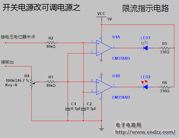
I found a circuit to limit the flow, as shown below:
It can be adjusted with the existing switching power supply, the cost is low, the precision is high, the stability is good, and the adjustment is much simpler than the ATX.
Cute and Small GPS Tracker for Pets
Features that already exist
âš« Tracking: It sends GPS (Location, speed) information to your application server with configurable report interval (moving or stationary).
âš« Geofence: It supports circle and polygon setting.
âš« SOS Button: Makes an SOS call or SMS message to a pre-configured phone.
âš« Mileage: Reports trip start, trip end and the mileage.
âš« 3-Axis Accelerometer: Using embedded accelerometer and carefully designed algorithm to detect the trip start/stop with accuracy.
âš« Battery Low Warning: When battery level is low, it will send low-battery alarm message.
âš« Cell-ID Based Location: Device reports cell-ID based location information if GPS signal is not available.
âš« Waterproof Case: IP65 waterproof.
âš« OTA (Over the Air): The device`s configuration, setting and firmware can be remotely upgraded.
âš« Mixed-mode: It will support 1-day-1-report mode, 1-hour check mode, power saving mode, super power saving mode, fix distance mode, fix interval mode and tracking mode to optimize the use of battery.
âš« WIFI-positioning: It will support WIFI feature for positioning.
âš« Multi-Platform: Customers can get device information through APP and web platform.
Other functions can be customized
Pets GPS Trackers,Animal GPS Tracker,Mini GPS Tracker,4G Pet GPS Trackers
eSky wireless Inc , https://www.eskygpsiot.com