
Keywords: wireless power load control system, central station, radio terminal controller
1 Introduction The wireless power load control system is an automation system that integrates power control, terminal power data collection, parameter distribution, and remote meter reading. Its application greatly improves the automation level of power grid operation and management, saving a lot of Manpower and material resources, and expanded the scope of monitoring data and improved the accuracy of monitoring data. The load control system was originally applied due to the shortage of electric energy in order to pull the brake to limit the power at the peak of power consumption. With the transformation of the contradiction between supply and demand in the power market, the function of the system has changed from control to load management. In fact, industrial users who have applied the load control system generally report that through the effective management of the company's electricity consumption, the company's economic benefits have been significantly improved.
2 The overall structure and function of the system
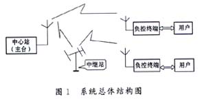
2.1 The overall structure of the system The significant difference between the wireless power load control system and the general load control system is that there is no need to lay communication cables between the central station and the terminal controller, it is mainly composed of three parts (as shown in Figure 1). (1) The central station (ie the main station) of the load control system is usually located in the regional power operation management department. The main station can communicate with the specified user by selecting the hardware address of the control terminal, and can also perform broadcast communication. (2) Wireless communication system, including the antenna mounted at the central station and the small antenna at the user and the relay station used for signal forwarding. (3) The load control terminal installed at the industrial user is used to collect electricity data, which is sent to the central station by the built-in radio station through the wireless communication network, and can accept the order of the central station to control the user's electricity consumption.
2.2 Main functions of the system
The main functions of the wireless power load control system are as follows.
· Data collection: Automatically collect the voltage and current of the power line, calculate the power factor, active and reactive power and power, and report the maximum and minimum load and their occurrence time. The graph and bar graph generated from the collected data are displayed on the screen, and can be connected to the printer to print out.
· Load control: It can realize power control and electric control for the user, and can also directly control the round trip of the user.
· Remote meter reading: Remotely read back the electricity consumption data measured by the double-rate energy meter installed by the user.
· Remote tuning: The main station remotely delivers control parameters to the user, including time period setting, PT (voltage transformer) transformation ratio, CT (current transformer) transformation ratio, meter pulse constant, and terminal timing.
· Call and information transmission: The terminal can apply for a call to the main station, and after approval, it can talk to the main station; the main station can actively select the user to talk, and can send short Chinese messages to the user.
Status alarm: It can reflect various statuses of system operation in real time, including the input of power control and electronic control, phase failure indication, and the status of trip switches of each round.
· Event record: record the abnormal state of the terminal, such as abnormal voltage and current and their occurrence time.
· Remote signaling function: feedback the opening and closing status of the 16-channel relay of the terminal to the central station.
· System management: It can register, query and modify user information, as well as query processing of operation records and historical data.
3 System hardware The terminal controller of the system has two separate PT and CT inputs, which can monitor the power consumption of the two busses at the same time. It is equipped with a CRT display, which can display the monitoring data graphically, because there are more display data , So select the data to be viewed through the keyboard.
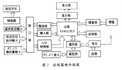
3.1 Working principle The hardware structure of the terminal controller is shown in Figure 2. Its main body is an STD industrial control computer, which uses a template structure to facilitate troubleshooting. The voltage and current of the power supply line are converted into digital signals by the A / D conversion board after being converted by PT and CT, and then sent to the V40 main board. The PT and CT ratios are sent to the terminal after being set by the main station. Actual voltage and current. The pulse signal sent by the pulse watt-hour meter is sent to the CPU through the input board, and the active and reactive power are calculated according to the pulse constant of the meter. The KG105 type radio station receives the command issued by the main station, sends it to the CPU through the communication board, and then the output board controls the action of the output relay, and then realizes the remote control trip operation. The remote meter reading is realized by the data collected by the radio station via the communication board in the Wasion meter, and the call data is the data calculated in the CPU. The CPU collects data every 1min. All calculation results are saved in the SRAM on the system board, which can save 24 hours of data. Therefore, the main station must recall the first day of data to the database of the central station the next day. Otherwise, the data on the first day will be lost.
3.2 The detection system for abnormal events analyzes the analog input of PT and CT. If one of the phase voltages is detected to be lower than a very small value, and the other two phase voltages are normal, the system reports the phase failure, indicating which one The phase is broken, and the time of occurrence is recorded. If the active power calculated by the system based on the analog input does not match the pulse power, the current abnormality is reported and the occurrence time is recorded. If a user steals power by cutting off the input of the pulse watt-hour meter, he can give instructions to prevent theft.
3.3 Coordinated control system for data calling and calling The main station calls users' data at regular intervals when the system is working normally. Remote transmission of electricity data is the most important function of the system. In order to prevent the main station from communicating with the terminal during the call For the normal transmission of data, the system has taken certain measures. There is a relay on the communication board. Under normal circumstances, the relay connects the data transmission channel between the CPU and the radio station. When the microphone button is pressed to talk, the relay automatically cuts off the data transmission and goes to the conversation channel. The microphone directly talks through the radio. When the time for pressing the call button reaches 30s, the relay automatically resets, forcibly ending the call, and resuming data transmission.
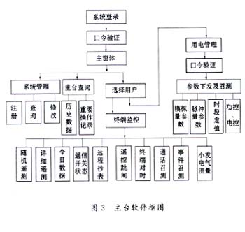
4 Master station software design The management software of the wireless power load control system is developed using the object-oriented programming tool VisualBasic 6.0. The system software block diagram is shown in Figure 3. After the system is started, it is required to enter the operator number and password. After verifying that it is correct, connect to the radio and enter the main form.
· Select users: select users to be operated, you can choose by name, address, keyword and industry classification. The address selection refers to the hardware address of the control terminal used by the user. The address is represented by a 4-digit hexadecimal number, such as 73B5.
· Important operation records: due to the remote control, time synchronization and other operations are of great importance, once an accident occurs, it will cause more serious consequences. The system software will record the database of the operation staff number, operation time, operation object and operation name of such operations. Facilitate tracing responsibility after an accident.
Interface processing: Terminal monitoring is the most important operation in the system. All these operations are done by calling the API function to access the RS232 port and communicating with the radio through this port.
· Electricity management: The electricity management mainly involves the setting of end-user electricity parameters, which is of great responsibility. Therefore, the system requires the operator to log in to the electricity management form only after entering a separate password.
5 Conclusion The application of the wireless power load control system has greatly reduced the workload of the staff in the power sector, avoided the errors that are prone to occur during manual meter reading, and strengthened the control and management of industrial users' power consumption by the power sector, making The load in the three periods of valley and valley tends to balance as much as possible. After applying this system, industrial users have facilitated the monitoring and recording of the power operation status of subordinate workshop departments, and the sensitive alarm function has also reduced the occurrence of electricity accidents to a certain extent.
Aerial bundled cable is a type of electrical cable that is used for overhead power distribution. It consists of several insulated conductors that are bundled together and covered by a protective sheath. The conductors are usually made of aluminum or copper and are insulated with cross-linked polyethylene or polyvinyl chloride .
ABC is commonly used in rural areas and in locations where underground cabling is not feasible or cost-effective. It is also used in urban areas for low voltage distribution and street lighting. ABC is designed to withstand extreme weather conditions, such as high winds, snow, and ice.
One of the main advantages of ABC is that it requires less maintenance than traditional overhead lines. The insulated conductors are less likely to come into contact with each other or with trees and other objects, reducing the risk of power outages and other issues.
ABC also offers improved safety compared to traditional overhead lines. The insulation on the conductors reduces the risk of electrical shock and fire, and the bundled design reduces the risk of accidental contact with the wires.
Overall, ABC is a reliable and cost-effective solution for overhead power distribution, particularly in areas where underground cabling is not feasible.
LV XLPE ABC Aluminium Cable,ABC aerial bundled cable,Aerial Bundled Electrical Cable,Spacer Overhead Insulated line Aluminum cable
Ruitian Cable CO.,LTD. , https://www.hbruitiancable.com