
A brief description
Over the years, programmable logic controllers (PLCs for short) have achieved a leap from wiring logic to memory logic from its generation to the present; its functions range from weak to strong, achieving progress from logic control to digital control; its applications range from small to small Large, a single device to achieve a simple control of the motion control, process control and distributed control and other tasks across. Today's PLC has greatly improved its capabilities in handling analog, digital computing, human-machine interfaces, and networks. It has become a mainstream control device in the field of industrial control and is playing an increasingly important role in all walks of life.
Second, the application of PLC
At present, PLC has been widely used in domestic and foreign steel, petroleum, chemical, electric power, building materials, machinery manufacturing, automotive, textile, transportation, environmental protection and cultural and entertainment industries. The use of PLC is mainly divided into the following categories:
1. Switching logic control
It replaces the traditional relay circuit and realizes logic control and sequence control. It can be used not only for the control of a single device, but also for multi-machine group control and automated assembly lines. Such as injection molding machines, printing presses, staple machines, machine tools, grinding machines, packaging production lines, plating lines and so on.
2. Industrial process control
In the industrial production process, there are some continuous changes such as temperature, pressure, flow rate, liquid level, and speed (ie, analog quantity). The PLC uses corresponding A/D and D/A conversion modules and various controls. Algorithm program to deal with analog, complete closed-loop control. PID regulation is a method of adjustment that is commonly used in closed-loop control systems. Process control has a very wide range of applications in metallurgical, chemical, heat treatment, boiler control and other occasions.
3. sport control
PLC can be used for the control of circular motion or linear motion. General use of a dedicated motion control module, such as single-axis or multi-axis position control module that can drive a stepper motor or servo motor, is widely used in various machinery, machine tools, robots, elevators and other occasions.

4. data processing
PLC has mathematical operations (including matrix operations, function operations, logic operations), data transmission, data conversion, sequencing, table lookup, bit operations and other functions, can complete the data collection, analysis and processing. Data processing is generally used in some large control systems such as papermaking, metallurgy, and food industries.
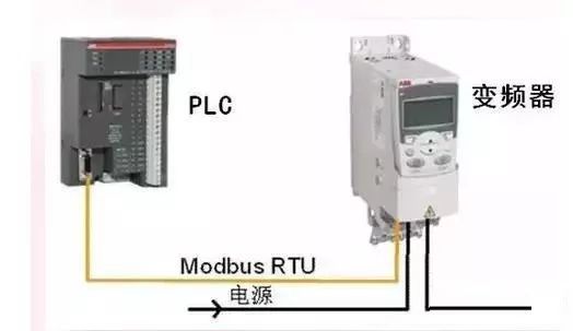
5. Communication and networking
PLC communication includes communication between PLCs and communication between PLC and other smart devices. With the development of factory automation networks, PLCs now have communication interfaces and communication is very convenient.
Third, the application of PLC features
1. High reliability, strong anti-interference ability
High reliability is the key performance of electrical control equipment. PLC adopts modern large-scale integrated circuit technology, adopts strict production technology to manufacture, the internal circuit adopts the advanced antijamming technology, has very high reliability. Using the PLC to form the control system, compared with the relay contactor system of the same scale, the electrical connection and switch contacts have been reduced to hundreds or even thousands of parts, and the failure is greatly reduced. In addition, the PLC has a hardware fault self-detection function, which can promptly issue an alarm message when a fault occurs. In the application software, the user can also program the fault self-diagnosis program of the peripheral device, so that the circuit and equipment other than the PLC can also obtain fault self-diagnosis protection. In this way, the entire system will have extremely high reliability.
2. Completely furnished, perfect function, strong applicability
PLC has developed into a series of products of various scales and can be used for industrial control applications of various scales. In addition to the logic processing functions, most PLCs have perfect data computing capabilities and can be used in various digital control fields. A large number of various functional units emerged, which allowed PLC to penetrate into various industrial controls such as position control, temperature control, and CNC. With the enhancement of PLC communication capabilities and the development of human-machine interface technology, it has become very easy to use PLC to form various control systems.
3. Easy to learn and use, highly welcomed by engineers and technicians
PLC is an industrial control equipment for industrial and mining companies. Its interface is easy, and the programming language is easy for engineers and technicians to accept. Ladder language graphics symbols and expressions and relay circuit diagram is quite close to open the door for industrial control of people who are not familiar with electronic circuits, do not understand computer principles and assembly language.
4. System design, small workload, easy maintenance, easy to transform
PLC replaces the wiring logic with storage logic, which greatly reduces the external wiring of the control equipment, greatly shortens the design and construction cycle of the control system, and also makes routine maintenance easier. More importantly, the same equipment is changed through changing programs. The production process becomes possible. This is particularly suitable for multi-species, small-batch production.
Fourth, need to pay attention to the problem in PLC application
PLC is a kind of equipment used for industrial production automation control, generally do not need to take any measures, can be used directly in the industrial environment. However, despite the above-mentioned high reliability and strong anti-interference ability, when the production environment is too harsh, the electromagnetic interference is particularly strong, or the installation is used improperly, it may cause a program error or an operation error, resulting in erroneous input and Caused by the wrong output, which will cause the device out of control and malfunction, which can not guarantee the normal operation of the PLC, to improve the reliability of the PLC control system, on the one hand requires the PLC manufacturer to improve the equipment anti-jamming capability; the other hand, the design requirements Serious attention has been paid to the installation, maintenance, use, and maintenance of the system. Multi-party cooperation can solve the problem and effectively enhance the system's anti-jamming performance. Therefore, pay attention to the following issues in use:
1. working environment
(1) Temperature
The PLC requires the ambient temperature to be 0~55°C. It should not be placed under the heat-generating component when installing. The space for ventilation and heat dissipation should be large enough.
(2) Humidity
In order to ensure the insulation performance of the PLC, the relative humidity of the air should be less than 85% (no condensation).
(3) Shock
Keep the PLC away from strong vibration sources and prevent frequent or continuous vibration with a frequency of 10 to 55 Hz. When the use of the environment can not avoid vibration, we must take measures to reduce vibration, such as the use of shock absorption rubber.
(4) Air
Avoid corrosive and flammable gases such as hydrogen chloride, hydrogen sulfide, etc. For environments where there is more dust or corrosive gases in the air, the PLC can be installed in a control room or control cabinet with good containment.
(5) Power supply
PLC has a certain resistance to the interference caused by the power line. In an environment with high reliability requirements or particularly severe power interference, an isolation transformer with a shield can be installed to reduce the interference between the equipment and ground. General PLC has a DC 24V output provided to the input, when the input uses an external DC power supply, should choose DC power supply. Because of the common rectification and filtering power supply, due to the influence of ripple, it is easy for the PLC to receive error information.
2. Interference and its source in the control system
On-site electromagnetic interference is one of the most common and most likely factors that affect the reliability of the system in a PLC control system. The so-called palliative rule is to treat the problem first and find out where the problem lies before it can propose a solution to the problem. Therefore, we must know the source of on-site interference.

(1) Interference sources and general classification
The interference sources that affect the PLC control system are mostly generated in areas where the current or voltage changes drastically. The reason is that the current changes to produce a magnetic field, which generates electromagnetic radiation to the device; the magnetic field changes to generate a current, and electromagnetic high-speed electromagnetic waves are generated. In general, electromagnetic interference is divided into common mode interference and differential mode interference according to different interference modes. Common-mode interference is the signal-to-ground potential difference, which is mainly formed by the superposition of the common-state (in the same direction) voltage induced by the grid string in, ground potential difference, and space electromagnetic radiation on the signal line. The common-mode voltage can be converted to differential-mode voltage through an asymmetrical circuit, directly affecting the measurement and control signals and causing damage to the components (this is the main reason for the high breakdown rate of some system I/O modules). This common-mode interference can be DC. Can also be exchanges. Differential mode interference refers to the interference voltage acting between the two poles of the signal, which is mainly caused by the coupling of the space electromagnetic field in the signal and the voltage formed by unbalanced circuit conversion common mode interference. This interference is superimposed on the signal and directly affects the measurement and control. Accuracy.
(2) The main sources and ways of interference in PLC system
Strong electric interference
The normal power supply of the PLC system is powered by the grid. Due to the wide coverage of the power grid, it will be subject to all space electromagnetic interference and induced voltage on the line. In particular, changes within the power grid, knife switch operation surges, start-stop of large-scale power equipment, harmonics caused by AC/DC transmission devices, and transient short-circuiting of the power grid are transmitted to the primary side of the power supply through transmission lines.
Cabinet interference
High-voltage electrical equipment in the control cabinet, large inductive loads, and chaotic wiring all easily cause some degree of interference with the PLC.
Interference from signal line introduction
Various types of signal transmission lines connected to PLC control systems, in addition to transmitting various types of effective information, always have external interference signals intruded. This interference mainly has two ways: First, through the power supply of the transmitter or the power supply of the common signal instrument, it is often overlooked; second, the signal line is interfered with by space electromagnetic radiation, that is, the signal line. The external inductive interference, which is very serious. The introduction of interference by the signal can cause abnormal I/O signal operation and greatly reduce the measurement accuracy. In severe cases, it can cause component damage.
Disturbance from grounded system disturbances
Grounding is one of the effective means to improve the electromagnetic compatibility (EMC) of electronic equipment. Proper grounding can not only suppress the influence of electromagnetic interference, but also inhibit the device from sending out interference. However, wrong grounding will introduce serious interference signals, which will make the PLC system unable to work properly.
Interference from inside the PLC system
It is mainly caused by the mutual electromagnetic radiation between the internal components of the system and the circuits, such as mutual radiation of logic circuits and their influence on analog circuits, interaction between analog ground and logic ground, and unmatched use of components.
Inverter interference
One is that harmonics generated during start-up and operation of the inverter will cause conductive interference to the grid, causing distortion of the grid voltage and affecting the power supply quality of the grid; second, the output of the inverter will generate strong electromagnetic radiation interference, affecting the normal operation of peripheral devices. .
3. Major anti-interference measures
(1) Reasonable power supply treatment, suppression of interference introduced by the power grid
For power grid interference introduced by the power supply, an isolation transformer with shielding ratio of 1:1 may be installed to reduce the interference between the equipment and the ground. An LC filter circuit may also be connected in series at the power input end. As shown in Figure 1
(2) Installation and wiring
â— The power line, control line, PLC power supply line and I/O line should be separately wired. The isolation transformer should be connected with PLC and I/O by double glue line. Separate the PLC's IO line from the high-power line. If it is necessary to separate the AC line and DC line in the same slot, if the conditions permit, the sub-slot alignment is the best. This can not only make it as large as possible. Space distance, and can minimize the interference.
â— PLCs should be kept away from strong sources of interference such as welders, high-power silicon rectifiers, and large-scale power equipment. They must not be installed in the same switch cabinet with high-voltage appliances. PLC should be far away from the power line in the cabinet (the distance between the two should be greater than 200mm). Inductive loads that are installed in the same cabinet as the PLC, such as relays with large power and coils of contactors, should be connected in parallel with the RC arc suppression circuit.
â— The input and output of the PLC should be routed separately. The switch quantity and analog quantity should also be laid separately. Shielded wires should be used for the transmission of analog signals. The shielding layer should be grounded at one or both ends. The grounding resistance should be less than 1/10 of the shielding layer resistance.
â— Do not use the same cable for AC output line and DC output line. The output line should be as far away as possible from the high voltage line and power line to avoid parallel operation.
(3) I/O terminal wiring
Input wiring
â— The input wiring should not be too long. However, if the ambient interference is small and the voltage drop is not large, the input wiring can be longer.
â— The input/output cable cannot use the same cable, and the input/output cable should be separated.
â— As far as possible, use a normally open contact form to connect to the input terminal, so that the programmed ladder diagram is consistent with the relay schematic diagram and is easy to read.
Output connection
â— Output wiring is divided into independent output and common output. In different groups, different types and voltage levels of output voltage can be used. However, the output in the same group can only use the same type of power supply with the same voltage level.
â— Since the output element of the PLC is packaged on a printed circuit board and connected to the terminal board, if the load connected to the output element is shorted, the printed circuit board will be burned.
â— When using a relay output, the size of the inductive load that is subjected to it will affect the service life of the relay. Therefore, when using an inductive load, a reasonable choice should be made or an isolation relay added.
â— The output load of the PLC may cause interference, so measures must be taken to control it, such as the freewheeling protection of the DC output, the resistance-capacitance absorption circuit of the AC output, and the bypass resistance protection of the transistor and the bidirectional thyristor output.
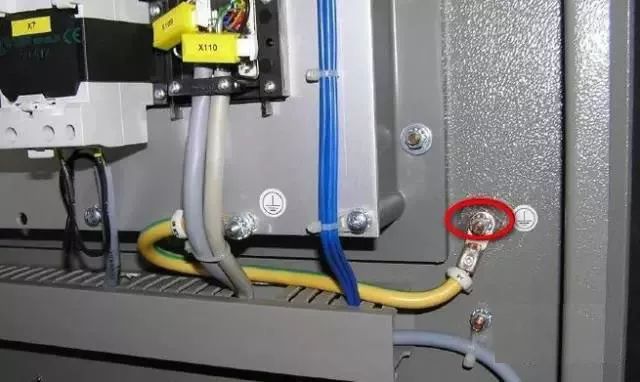
(4) Correctly select the grounding point and improve the grounding system
Good grounding is an important condition for ensuring the reliable operation of the PLC, and accidental voltage surge hazards can be avoided. The purpose of grounding is usually two, one is for safety, and the other is to suppress interference. A perfect grounding system is one of the important measures against electromagnetic interference in the PLC control system.
The ground of the PLC control system includes system ground, shield ground, exchange ground, and protection ground. The disturbance of the grounding system to the PLC system is mainly due to the uneven distribution of the potential of each grounding point. There is a difference in ground potential between different grounding points, which causes the ground loop current and affects the normal operation of the system. For example, the cable shield must be grounded at one point. If both ends of the cable shields A and B are grounded, there is a difference in ground potential and a current flows through the shield. When an abnormal state such as a lightning strike occurs, the ground current will be greater.
In addition, the shielding layer, grounding wire and ground may constitute a closed loop. Under the effect of changing the magnetic field, inductive current will appear in the shielding layer, and the signal loop will be disturbed through the coupling between the shielding layer and the core wire. If system grounding and other grounding processes are confusing, the generated ground current may produce unequal potential distribution on the ground line, affecting the normal operation of logic circuits and analog circuits within the PLC. The logic voltage disturbance tolerance of PLC work is lower, the logic ground potential distribution interference easily affects PLC logic operation and data storage, causes the data to be chaotic, the procedure runs away or crashes. The distribution of the simulated ground potential will lead to a decrease in measurement accuracy, causing serious distortion and malfunction of the signal measurement and control.
â— Safely or power ground
Connect the ground of the power cord and the connection of the cabinet to a safe ground. If the power supply leaks or the cabinet is charged, it can be led into the ground from a safe ground and will not cause harm to people.
â— System ground
The PLC controller is grounded for the same potential as the controlled devices. The grounding resistance value shall not be greater than 4Ω. Generally, the negative terminal of the switching power supply in the PLC equipment system and the control cabinet shall be connected together as the control system ground.
â— Signal and shield ground
Generally speaking, the signal line must have a unique reference ground. When the shielded cable encounters the possibility of conductive interference, it must be grounded on the local or control room to prevent the formation of a "ground loop." When the signal source is grounded, the shielding layer should be grounded on the signal side; when it is not grounded, it should be grounded on the PLC side; when there is a connector in the middle of the signal line, the shielding layer should be firmly connected and insulated, and must be grounded at multiple points; When the shielded twisted pair of point signal is connected with the multi-core twisted pair general shielded cable, the shielding layers should be connected with each other and be insulated and the appropriate single point contact of the grounding point should be selected.
(5) Inhibition of Inverter Interference
Inverter interference processing generally has the following methods:
The addition of isolation transformers is mainly aimed at conducted interference from the power supply, and can block most of the conducted interference before the isolation transformer.
Using a filter, the filter has a strong anti-jamming capability, and also has the ability to prevent the transmission of interference from the device itself to the power supply, and some also have a spike voltage absorption function.
The use of output reactors to increase the AC reactor between the inverter and the motor is mainly to reduce the electromagnetic radiation generated by the inverter output during the energy transmission process, affecting the normal operation of other equipment.
The interference in the PLC control system is a very complicated problem. Therefore, in the anti-jamming design, various factors should be comprehensively considered, and the anti-interference can be reasonably and effectively suppressed before the PLC control system can work normally. With the continuous expansion of the PLC application field, how to use the PLC efficiently and reliably has also become an important factor in its development.
V. Conclusion
In the future, PLC will have even greater development. The variety of products will be more abundant, and the specifications will be more complete. Through the perfect man-machine interface and complete communication equipment, it will better meet the needs of various industrial control applications. PLC will serve as an automation control network and The important part of the international general network will play an increasingly important role in the field of industrial control.
57 Jack.China RJ11 Jack 1X5P,RJ11 Connector with Panel supplier & manufacturer, offer low price, high quality 4 Ports RJ11 Female Connector,RJ11 Jack 6P6C Right Angle, etc.
The RJ-45 interface can be used to connect the RJ-45 connector. It is suitable for the network constructed by twisted pair. This port is the most common port, which is generally provided by Ethernet hub. The number of hubs we usually talk about is the number of RJ-45 ports. The RJ-45 port of the hub can be directly connected to terminal devices such as computers and network printers, and can also be connected with other hub equipment and routers such as switches and hubs.
RJ11 Jack 1X5P,RJ11 Connector with Panel,4 Ports RJ11 Female Connector,RJ11 Jack 6P6C Right Angle
ShenZhen Antenk Electronics Co,Ltd , https://www.antenkcon.com