
Some industrial data links that require RS-232 data transmission over long distances or between multiple RS-232 applications typically use RS-232 to RS-485 converters. Despite the high signal swing of up to ±13V, RS-232 is still an unbalanced or single-ended interface and is itself highly susceptible to noise. Its bus length is limited to about 20 meters (60 feet). Although full-duplex data transmission is allowed (simultaneous signal lines are used to simultaneously transmit and receive data), RS-232 does not support connecting multiple nodes on the same bus.
In sharp contrast, RS-485 is a balanced interface that uses differential signaling to provide high common-mode noise immunity. Therefore, extending the RS-232 data link transmission distance and achieving multi-bus node connection requires conversion to an RS-485 signal through an interface converter (see Figure 1).
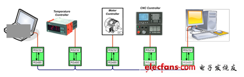
Figure 1 Conversion of short-range, point-to-point data links to long-distance, multi-point networks
Figure 2 shows a schematic of a low-power, isolated converter design. Here, the RS-232 serial port of a personal computer (PC) is connected to the SUB-D9 interface on the left side.
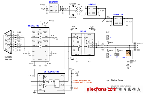
Figure 2 Isolated RS-232 to RS-485 converter using automatic directional control.
The PC serial port contains an RS-232 driver and receiver chip that converts its internal 5V logic signal to a higher ±8V to ±13V level at the interface. These high voltage bus signals are then converted back to standard logic levels by another RS-232 chip to communicate with the RS-485 transceiver.
In the transmit direction, the 485 transceiver converts the logic signal from the RS-232 receiver output into a differential bus signal. In the receive direction, it converts the differential bus signal into a single-ended, low-voltage signal that enters the input of the RS-232 driver.
The RS-485 transceiver includes a capacitive isolation layer that galvanically isolates between the bus and logic control terminals, thereby eliminating ground currents between bus nodes.
On the bus side, this converter design has several components that ensure reliable data transfer. Jumpers J1 and J2 activate the fail-safe bias network during bus no load. If this converter is installed on the bus side, a 120 ohm terminating resistor can be implemented via jumper J3.
A transient suppressor protects the transceiver from dangerous transient overvoltages by clamping the ground potential. In order to shunt the transient current to ground, a high voltage capacitor is required to provide AC coupling between the floating bus ground and the protective ground (PE). In general, we use a short single-core conductor (18 AWG) to connect to the PE or chassis ground.
Signal path isolation also requires power isolation. Here, we adjust the bus supply (3.3V to 10V) through a low dropout voltage regulator (LDO). It is then used for transceiver bus power (Vcc2) and an isolated DC/DC converter. This converter consists of a transformer driver, an isolation transformer, and a secondary LDO (powering the logic circuitry).
Older converter designs sometimes use a request to send signal (RTS) to switch the RS-485 transceiver from slave mode to transmit mode. However, in some computer applications, the RTS generation interface software runs under Windows®, not in real time. Therefore, if Windows decides to use its processing time for another application, screen saver, or anti-virus software, RTS may not be able to switch the transceiver back to receive mode in real time, so the data sent by another bus node may Lost.
The converter design shown in Figure 2 eliminates the possibility of this by implementing an automatic directional function. This automatic direction selection detection is achieved by a one-shot trigger. The output of the trigger is triggered high by the 232 receiver output. By default, the RS-485 transceiver is in receive mode. When the monostable output goes high, it switches the transceiver to transmit mode.
The time constant of this monostable output is defined by an RC network. The data rate is 9600 bps, C = 220 nF at 2ms high time, and R = 10 kOhm; the data rate is 1200 bps, and R = 100 kOhm at 20ms high time. When the high state time is over, the monostable output goes back low again, switching the transceiver back to receive mode. Although the auto-select feature relies on the data rate, it is still a reliable way to prevent data loss.
All black solar panels or black frame Solar Panel, power range around 400w to 460w which is higher solar panel efficiency the front black or front and back are both black.
All black solar panel data
| mono type | mono crystalline half cut cell |
| power range | 400watt to 460watt |
| dimensions | 1176*1134*30mm |
| type | monofacial type or bifacial type |
Product details and pic


All Black Solar Panel,Trina Solar Panel Vertex S,Mono Crystalline Pv Modules,Full Black Solar Panels 420Watt
PLIER(Suzhou) Photovoltaic Technology Co., Ltd. , https://www.pliersolarpanel.com