
Reading
The electrical control system is generally called the secondary control circuit of the electrical equipment. Different equipment has different control loops, and the control method of high-voltage electrical equipment and low-voltage electrical equipment is also different. Today, Xiaobian learns the basic knowledge of electrical control systems with everyone.
The function and composition of the electrical control system
The main function
In order to ensure the reliability and safety of the primary equipment operation, a number of auxiliary electrical equipments are required to serve them, and a combination of several electrical components capable of achieving a certain control function is called a control loop or a secondary loop. These devices must have the following features:
(1) Automatic control function. The volume of high-voltage and high-current switchgear is very large. Generally, operating systems are used to control the points and closings. In particular, when the equipment fails, it is necessary to switch off the circuit automatically, and a set of automatic control electrical equipment is required. Automatic control of power supply equipment.
(2) Protection function. Electrical equipment and lines will malfunction in the course of operation, the current (or voltage) will exceed the scope and limits of the equipment and the line allows work, which requires a set of detection of these fault signals and automatic adjustment of the equipment and lines (disconnected, Switching, etc.) protection devices.
(3) monitoring function. Electricity is invisible to the eyes. Whether a device is powered or off, and it cannot be distinguished from the outside, it is necessary to set various audiovisual signals, such as lighting and sound, to perform electrical monitoring on the primary device.
(4) Measurement function. Lights and sound signals can only qualitatively indicate the working status of the equipment (electricity or power failure). If you want to quantitatively know the working conditions of electrical equipment, you need to have a variety of instrument measuring equipment, measuring various parameters of the circuit, such as voltage , current, frequency, and power size.
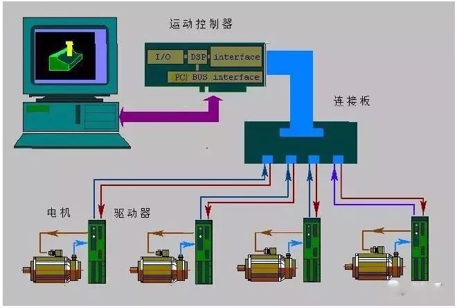
In the operation and monitoring of equipment, most of the traditional operating components, control devices, instruments, and signals can be replaced by computer control systems and electronic components, but there is still a certain range of applications in small devices and locally controlled circuits. . This is also the basis for the circuit to realize the automatic control of the microcomputer.
System composition
The basic circuit of the commonly used control circuit consists of the following components.
(1) Power supply circuit. Power supply circuit power supply AC380V and 220V and many other.
(2) Protection circuit. The protection (auxiliary) circuit has a variety of operating power sources such as single-phase 220, 36V or DC 220, 24V, etc. It protects electrical equipment and lines from short-circuit, overload and voltage loss, and is protected by fuses, thermal relays, and loss-voltage coils. , rectifier components and voltage regulator components such as protection components.
(3) Signal loop. The circuit that can timely reflect or display the normal and abnormal working status information of equipment and lines, such as different color signal lamps, different sound audio equipment, etc.
(4) Automatic and manual circuits. In order to improve work efficiency, electrical equipment generally has automatic links. However, in the process of installation, commissioning and emergency handling, manual links must also be set up in the control lines, and automatic and manual conversions can be achieved through combination switches or transfer switches.
(5) brake parking circuit. Cut off the circuit power supply, and take some braking measures to make the motor quickly stop the control link, such as energy consumption braking, power supply reverse braking, reverse pull braking and regenerative braking.
(6) Self-locking and latching circuits. After the start button is released, the circuit remains energized, and the electrical link in which the electrical equipment can continue to work is called the self-locking link. For example, the contactor's moving contact is connected in series with the coil circuit. Two or more than two electrical devices and components, in order to ensure the safety and reliability of the operation of the equipment, only one power-activated start, and the other can not start the protection of power links, called the lock-out link. For example, the two movable contacts of the two contactors are respectively connected in series in the other coil circuit.
What is an electrical interlock? Self-locking?
Electrical interlock
The interlocking in electrical control is mainly set to ensure the safe operation of electrical appliances. It is mainly controlled by two electrical devices to form an interlock. There are mainly three ways to achieve it, one is electrical interlocking. The second is mechanical interlocking, and the third is interlocking of electrical machinery.
â–² interlock
Electrical Interlock: The normally closed contacts of the two relays are connected to the coil control circuit of the other relay. In this way, a relay is electrically actuated, and no closed circuit is formed on the other relay coil. However, mechanical linkages can also be used to achieve this action. The third is interlocking of electrical and mechanical linkages. Such as high-voltage cabinet power, switch is not disconnected, isolation switch will not open, the above can not be opened on the ground can not close the switch, pull the switch to open the ground, you can not open the high voltage cabinet door, you can not switch The check waits until it works. The electrical interlock is achieved through the contacts of the relay and the contactor. For example, when the motor rotates forward, the contact of the forward contactor cuts off the reverse button and the electrical path of the reversing contactor. Mechanical interlocking means interlocking with mechanical components. For example, if two switches cannot be closed at the same time, the mechanical lever can be used. When one switch is closed, the other switch is mechanically stuck and cannot be closed. Electrical interlocking is relatively easy to implement, flexible and simple, and two interlocked devices can be installed in different locations, but the reliability is poor. Mechanical interlocks are highly reliable, but they are complex and sometimes even impossible. The two devices that are normally interlocked are to be installed in close proximity.
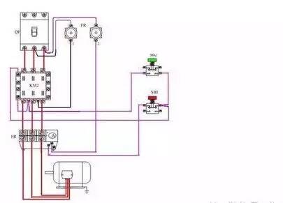
After the common power supply is restored, it can automatically switch to a common power supply (of course, it can also not be switched). The electrical realization of this function is called an electrical interlock, which can also be called an electrical interlock. There are many places where forward rotation and reverse rotation of the motor are required. For example, the opening and closing of the gate is the control of the motor's rotation and reverse rotation. The forward rotation and reverse rotation of the motor are realized by inverting the phase sequence of the power supply. During forward operation, reverse operation will cause a short-circuit between phases and burn out the electrical equipment. This prevents this from happening. Connect the auxiliary normally-closed contact of the AC contactor to the motor during forward rotation. In the reversed control loop, the auxiliary contact of the inverting AC contactor is connected in series in the control circuit of the motor turning down. When the motor rotates forward, the control of the reverse motor is cut off by the normally closed auxiliary contact of the AC contactor. Loops prevent reversals from being put into operation.
During the reversal operation, the normally closed auxiliary contact of the AC contactor is used to shut off the control circuit of the forward rotation of the motor, so that the forward rotation operation does not work.
The circuit is divided into a main circuit also called a primary circuit (power supply wiring) and the control circuit is also called a secondary circuit, and the secondary circuit is to control a primary circuit.
The AC contactor is a control element. It has a control coil inside, which can be AC220V voltage or AC380V voltage. After power on, it can be closed, and once the main circuit is connected to make the motor work. The on-off line of the control coil is a control control line.
When the electrical component is not energized, the closed contact is called a dynamic break normally closed contact, and the disconnected contact is called a moving normally open contact. The contacts of the main circuit can pass a large current, and different sizes of AC contactors are selected according to the size of the motor. The auxiliary contacts are connected inside the control loop, so the current is limited to 5A.
Self-locking electrical control circuit
The characteristics of the contactor - the contactor generally has 6 posts, of which 3 are normally open contacts, 2 are normally closed contacts and 1 is a coil. When the coil is energized, all normally open contacts close and all normally closed contacts open.
For easier understanding, look at the circuit diagram first:
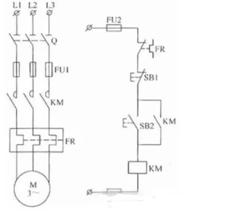
â–²Self-locking
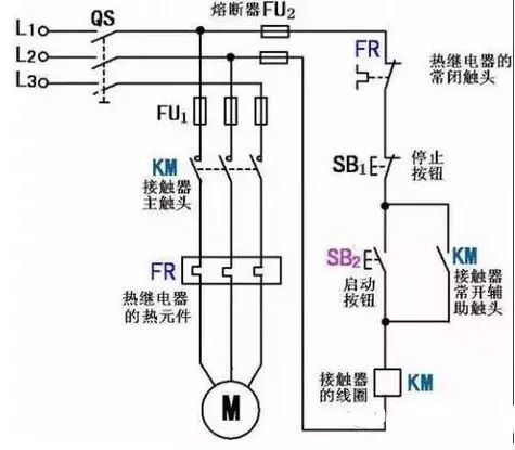
In this figure, the left side is the main circuit, and the right side is the secondary circuit (we've omitted the connection between the main circuit and the secondary circuit for clarity). At this point, we only look at the secondary circuit. SB2 is the normally open button, the lower KM is the contactor coil, and the upper KM is the contactor normally open contact.
If there is no contactor's participation, that is, there is no place marked with KM in the figure, SB2 is energized in the loop when it is pressed, and is de-energized when it is released (normally open button, and the start button is normally open). So we connected the contactor coil and connected the normally open contact in parallel with the SB2. As a result, when the SB2 is pressed, the coil is momentarily energized to close the normally open contact to ensure that the circuit is still powered when the SB2 is released.
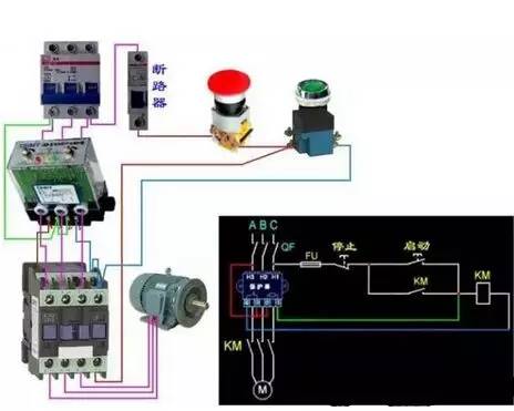
The most common self-locking circuit
â–² The most common circuit - self-locking circuit
working principle
1
start up
When the motor starts, close the power switch QS and turn on the power of the entire control circuit.
Press the start button SB2, its normally open point is closed, the contactor coil KM can be pulled by electricity, and is connected to the auxiliary normally open at both ends of SB2 and closed at the same time.
In the main circuit, the main contact is closed and the motor is connected to the three-phase AC power to start rotation.
In the secondary circuit: After SB2 is pressed, electricity is sent to the KM coil. After the KM auxiliary contact is turned on, it also supplies power to the KM coil, thus forming two-way power supply.
When the SB2 start button is released, although the SB2 has been disconnected all the way, the KM coil keeps energizing the coil through its own auxiliary contact path, thus ensuring that the motor continues to operate.
This way of relying on the contactor's normally open auxiliary contacts to keep its coils energized is called contactor self-locking, also called electrical self-locking. This auxiliary self-locking normally open contact is called a self-locking contact. This circuit is called a self-locking circuit.
2
stop
To stop the motor, press the SB1 button. The contactor KM coil is de-energized. The KM main contact and auxiliary contact are disconnected. The motor main circuit and control circuit power are cut off and the motor stops working.
When the SB1 button is released, the normally closed contact of the SB1 closes again under the action of the return spring, and although it has returned to the original normally closed state, the original KM self-locking contact has already been disconnected as the KM coil is turned off. The contactor can no longer rely on the self-locking contacts.
3
Circuit protection
The fuses FU1, FU2 are short circuit protections for the main circuit and the control circuit, respectively. The thermal relay FR serves as a long-term overload protection for the motor.
Electric control system commonly used protection links
In addition to meeting the requirements of the production machinery process, the electrical control system should also ensure long-term, safe, reliable and trouble-free operation of the equipment, and protect the power supply equipment and the motor in the event of any failure or abnormal operation of the system. Therefore, the protection link is an indispensable part of all electrical control systems. It is used to protect the motor, power grid, electrical equipment and personal safety.
Short circuit protection
Damage to the insulation of motors, electrical appliances, and wires can cause short-circuit accidents when the line fails. Large short-circuit currents and electrical power may damage electrical equipment. Therefore, it is required that the control circuit can quickly cut off the power supply in the event of a short-circuit fault. Commonly used short-circuit protection components include fuses and low-voltage circuit breakers. The motor short-circuit protection components can be installed as follows:
1) In a system that is directly earthed at a neutral point, it should be installed on each phase.
2) In the neutral grounding system, fuses shall be installed on each phase when they are protected; on low voltage circuit breakers, they shall be installed on not less than two phases.
2. Overload protection
Long-term overload operation of the motor, winding temperature rise will exceed its allowable value, resulting in aging of the insulation material, reduced life expectancy, serious damage to the motor will occur, the greater the overload current, the shorter the time allowed to allow temperature rise. Commonly used overload protection elements are thermal relays. For high-power, important motors, an inverse-timed over-current relay should be used.
Due to the thermal inertia, the thermal relay will not be instantaneously affected by the short-time overload surge current or short-circuit current of the motor. Therefore, when the thermal relay is used for overload protection, short-circuit protection must also be provided, and the short-circuit protection fuse must be selected. The rated current of the device melt should not exceed 4 times the rated current of the thermal relay heating element. Since the overload protection characteristics are different from the over-current protection characteristics, it is not possible to use an over-current protection method for overload protection.
3. Over current protection
Overcurrent protection is widely used in DC motors or wound asynchronous motors. For three-phase cage asynchronous motors, overcurrent protection is not provided because short-time overcurrent will not have serious consequences.
Over-current protection is often caused by incorrect startup and excessive load. Generally, it is smaller than short-circuit current. It is more likely to generate over-current in motor operation than short circuit, especially in frequent forward/reverse start-up. This is especially true for short-duration duty motors.
It must be emphasized that although short-circuit, over-current, and overload protection are all current protection, they cannot be replaced by each other due to different fault currents, operating values ​​and protection characteristics, protection requirements, and the use of components.
4. Loss of voltage protection
If the power supply voltage disappears for some reason during the normal operation of the motor, if the motor is started automatically when the power supply voltage is restored, the production equipment may be damaged and personal accidents may occur. In addition, on the power supply system's power grid, there are many motors and other electrical equipment that start up on their own can also cause unallowable over-current and instantaneous network voltage drop. In order to prevent the voltage from recovering, the protection set by the motor itself or the electrical component being put into operation is called the protection of the loss voltage.
The start-up and stop control steps using the contactor and the button control have the function of voltage drop protection. Because when the power supply voltage disappears, the contactor will automatically release and cut off the motor power supply; when the power supply voltage recovers, the self-locking contactor of the contactor will be disconnected and will not start automatically. If the contactor is controlled by a manual switch or a master controller that cannot be reset, a special zero-voltage relay must be used. Once the voltage is lost during operation, the zero-voltage relay is released and the self-locking circuit is disconnected. When the power supply voltage recovers, it will not start automatically.
5. Undervoltage protection
When the motor is running normally, excessive reduction of the power supply voltage will cause some electrical appliances to be released, causing the control circuit to work abnormally or even causing an accident. When the grid voltage is too low, if the motor load is constant, it will cause the motor current to increase, causing the motor to heat up and even burn out the motor in severe cases. In addition, too low supply voltage can cause the motor speed to drop, even stop. Therefore, when the power supply voltage drops below the allowable value, protection measures must be taken to cut off the power in a timely manner. This is undervoltage protection. This is usually achieved using undervoltage relays.
Electrical Control System Design Requirements and Steps
01
aim of design
The main purpose of electrical design is to understand the general electrical control system design process, design requirements, work content to be completed, and specific design methods through the design practice of an electrical control device for a production facility. The design also helps to review and consolidate what has been learned in the past and achieve the purpose of flexible application. The electrical design must meet the requirements of the production equipment and production process. Therefore, before the design, it is necessary to understand the purpose, structure, operation requirements, and process of the equipment. In this process, the overall concept of the design work must be cultivated.
Electrical design should focus on competence training. While independently completing design tasks, we must also pay attention to the cultivation and improvement of other aspects of capabilities, such as the ability to work independently and creativity; comprehensive use of professional and basic knowledge to solve practical engineering techniques. The ability of the problem; the ability to access book materials, product manuals, and various reference books; the ability of engineering drawings; the ability to write technical reports and compile technical data.
02
Design requirements
In order to ensure the successful completion of design tasks, the following points should also be achieved:
(1) After accepting the design task, the design task book and work schedule plan should be drawn up according to the design requirements and the design content to be completed, the workload to be completed in each phase should be determined, and the time should be properly arranged.
(2) In the process of determining the plan, it is necessary to proactively ask questions in order to obtain guidance teachers' help. At the same time, opinions should be widely discussed and based on sufficient evidence. In the specific design process to think more, especially the main parameters, to be calculated and demonstrated.
(3) The drawing of all electrical drawings must comply with the relevant national standards, including lines, drawing symbols, item codes, circuit labels, technical requirements, title bar, component list, and drawing folding and binding.
(4) The specification requires smooth, concise, well-written and neat writing.
(5) All design tasks should be completed within the stipulated time.
(6) If the conditions permit, test and verify their own design lines and consider the possibility of further improvement.
03
Design task
Course design requirements are expressed in the form of a design assignment book. The design assignment book should include the following:
(1) A brief description of the equipment's name, purpose, basic structure, operating principle, and process.
(2) Drag method, movement sequence of moving parts, various movement requirements and control requirements.
(3) Interlocking and protection requirements.
(4) Auxiliary requirements such as lighting, instructions, and alarms.
(5) Patterns that should be drawn.
(6) Specification requirements.
The central task of principle design is to draw electrical schematics and select electrical components. The purpose of the process design is to obtain the required construction drawings for the electrical equipment manufacturing process. There are many types and quantities of drawings. The design mainly includes the overall configuration diagram of electrical equipment, layout drawings of electrical board components, wiring diagrams, control panel layout drawings, wiring diagrams, electrical boxes, and main processing parts (electrical installation baseplates, control panels, etc.) For practice objects. For each designer, only one part needs to be completed. The principle circle and artwork should be drawn according to requirements. The component layout should mark the overall dimensions, installation dimensions and relative position dimensions. The number of the wiring diagram should be the same as that of the schematic diagram. All the inlet and outlet numbers, wiring specifications, and connection methods of the inlet and outlet wires (using terminal boards or patch panels) must be marked.
9H Flexible Glass Screen Protector
This kind of Flexible Glass Screen Protective Film is made of nano-glass material and is an indispensable device for people who often drop their mobile phones. The Flexible Protective Film can be perfectly fixed on the mobile phone to completely protect the mobile phone screen to prevent scratches and cracks on the edge of the mobile phone screen.
The surface hardness is 9H hardness. Sharp objects (such as knives and keys) will not scratch the surface.
The high transparency of 0.22mm ensures that you can view all screen content clearly and clearly, while providing unique touch screen sensitivity.
The Screen Protection Film has an "oleophobic and waterproof" coating that prevents dust and fingerprint smudges and ensures that it can be easily removed.
In case the screen is damaged, the Screen Protector will break into small pieces that are not sharp, which is much safer than other glass screen protectors on the market.
If you want to know more about 9H Flexible Glass Screen Protector products, please click product details to view the parameters, models, pictures, prices and other information about 9H Flexible Glass Screen Protector products.
Whether you are a group or an individual, we will try our best to provide you with accurate and comprehensive information about 9H Flexible Glass Screen Protector!
9H Flexible Glass Screen Protector, 9H Screen Protector, 9H Flexible Protective Film, Flexible Protective Film
Shenzhen Jianjiantong Technology Co., Ltd. , https://www.jjttpucuttingplotter.com