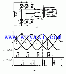
In the three-phase controllable rectifier circuit, it is very important to select the synchronous power supply of the trigger circuit. Only when the synchronous power supply is correctly selected can each thyristor sequentially trigger the conduction in sequence at a specified time. The choice of synchronous power supply is related to three factors: (1) the form of the rectifier circuit and the connection of the rectifier transformer winding; (2) the connection of the synchronous transformer winding; (3) the phase of the synchronous power supply voltage and the phase of the trigger pulse in the trigger circuit The relationship between. Taking the three-phase full-control bridge rectifier circuit as an example, the method of selecting the synchronous power supply is described.
Synchronous power supply selection The three-phase bridge type full-controlled rectification circuit shown in Figure 1(a), when the phase control angle a = 0 °, the trigger pulse phase of the six thyristors T1 ~ T6 must be as shown in Figure 1 (b) The order is arranged in order to synchronize the trigger pulse with the main circuit power supply. Synchronization of the trigger pulse with the main circuit power supply is achieved by correctly selecting the phase of the synchronous power supply, provided that the frequencies are the same.
Since the trigger circuit is different, the phase of the required synchronous power supply is also different. The trigger circuit of the sawtooth wave with the synchronous voltage described above is taken as an example to illustrate the selection of the synchronous power supply. 
figure 1
In the trigger circuit of the sawtooth sync signal, the zero crossing of the synchronous voltage uT is the starting point of the sawtooth wave. In order to make the phase shift range of the pulse fall in the region where the thyristor can trigger conduction, the starting point of the sawtooth wave must be aligned with the control angle a=0 of the thyristor, so the phase angle of the synchronous power supply uT wt=180° must be aligned. a = 0 °. Therefore, the trigger circuit of the thyristor T1 connected to the main circuit ua phase should select the synchronous voltage of the phase 150° ahead of ua as the synchronous power supply, so that the trigger pulse of T1 can appear at 30° of the ua waveform.
According to this relationship, after the connection mode of the main transformer is determined, the connection of the synchronous transformer and the synchronous power supply of each phase trigger circuit can be further selected. According to the voltage vector diagram of the rectifier transformer and the synchronous transformer, it can be determined that the synchronous power supply voltage of the trigger circuit of the thyristor T1 is a synchronization signal of ua 150° ahead. If the connection of the rectifier transformer is changed or the trigger circuit is changed, the connection of the synchronous transformer and the synchronous power supply of each trigger circuit should also be changed accordingly to ensure that the trigger circuit can start at the natural commutation point of the main power phase voltage. Generate a pulse.
Determination of initial phase The production machinery requires the drag system to have zero when the main circuit and control circuit are connected to the power supply. When the control voltage is zero, the output voltage of the controlled rectifier device should also be zero. The phase of the pulse when the rectified voltage is zero is called the initial phase of the trigger pulse. The initial phase angle of the trigger pulse is related to the form of the main circuit and the nature of the load. Such as three-phase half-controlled bridge rectifier circuit, when a = 180 °, the rectified voltage Ud = 0; and three-phase full control bridge rectifier circuit, resistive load a = 120 °, rectified voltage Ud = 0; in the large inductance Under the condition that the load makes the current continuous, the rectified voltage Ud=0 when a=90°; if the inductive load is not enough, the initial phase angle is between 90° and 120°.
In order to achieve the purpose of the initial phase when the control voltage UK=0, the offset voltage is added to the trigger circuit, and the initial phase of the trigger pulse is adjusted by changing the magnitude of the offset voltage. The polarity of the offset voltage is always opposite to the polarity of the sawtooth voltage.
Silent Generator Standard Specification:
- Large Integral Fuel Tank.
- Overspeed Shutdown.
- Extra Large Access Doors.
- Manual or Automatic Start.
- Available with or without the trailer.
- High Water Temperature Shutdown.
- Overcrank Lockout.
- Battery Included:
- Voltage Selections Three-position switch No reconneciion required.
- Low Oil Pressure Shutdown.
- Full Featured Control Panel.
- Fuel Water Separators.
- Single Point Lifting Eye
- Silent Canopy
- 20FT & 40FT Container Type Generators
Silent Generator,Silent Diesel Genset,Ontainer Generator,Portable Generator
Guangdong Superwatt Power Equipment Co., Ltd , https://www.swtgenset.com
