If there is no good architecture, transplantation will be a very painful thing.
Without a good architecture, reuse is the biggest problem, and it is impossible to reuse the original code to a greater extent.
If there is no good structure, once the driver is changed, everything must be changed, which is time-consuming, laborious and error-prone.
If there is no good architecture, the application layer is interspersed with the code of the hardware driver layer, it will seem to be chaotic, the logic is unclear, and the code maintenance will be very difficult.
Nowadays, children all love to play the game of building blocks, which can be assembled one by one to quickly form a variety of different models. Today's product design rarely starts from scratch. Most of them reuse existing mature modules and focus on a certain area of ​​expertise.
To achieve the code logic of embedded applications is clear, and to avoid repetitive wheel building, how can you do without a good application architecture!
The API is divided into the driver layer and the application layer API, instead of all programs calling the driver layer API. (Calling the driver layer API in the entire application will cause driver calls in the application to be seen everywhere, unable to be transplanted and reused to the maximum extent)
First divide an application into functional modules, and layer the overall structure, and then design functionally independent modules (such as algorithm modules, file library modules, communication library modules), and open public interfaces on the modules.
The driver layer provides a public interface for the upper layer to call. Each function module can be compiled independently (for example, the algorithm module is pure ANSI C, which can be reused on any platform), or call the driver layer interface (the file library module calls the driver to read and write Flash), in a word, in short, encapsulate each function independently The reusable functional modules.
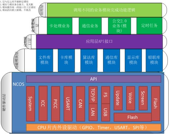
The overall is divided into hardware driver layer-->functional module layer-->application interface layer-->business logic layer-->application layer
Schematic block diagram of the overall structure:

The application layer, the overall operating framework of the program, organizes and calls business logic. Several tasks can be achieved with a certain embedded operating system. Such as timing tasks, card processing tasks, menu tasks, communication tasks.
Business logic layer, such as CPU card processing, Ministry of Transport card processing, UnionPay card processing, M1 card processing, communication record upload, blacklist download, fare parameter download, etc.
The application interface layer provides a public api interface application interface for the upper layer to call. These interfaces can also be opened by the function modules of the lower layer, and the application interface layer is responsible for summarizing.
The functional module layer can encapsulate different functional modules. Such as algorithm library, file library, communication library, UnionPay library, provide the interface of the application interface layer upward, and call the driver interface downward.
The hardware driver layer is composed of various driver modules and provides a unified interface upwards.
Follow some conventions: 1. The interface provided by each module must be unified, and the original interface can only be added in the future.
2. Modules are independent of each other, do not affect each other, cannot call each other, and can only call the interface below it.
3. The layers are composed of modules, and no cross-level calls are allowed between layers. For example, you cannot see the code that directly calls the driver layer in the application layer.
4. The module can continue to be layered, such as the interface layer, the driver layer, and the hardware layer.
If the driver changes, or if you change to a different platform, you only need to change the driver layer, and the application layer will not be affected.
If the function module is changed, only the function module needs to be upgraded, other modules will not be affected, and the application layer will not be affected.
After designing in accordance with this logic, the main work is in the business logic layer. The application layer is the overall process and framework of the program, mainly calling the business logic layer to implement different functions.
Our current code structure is basically based on this idea.
Hardware driver layer --> function module layer --> application interface layer --> business logic layer --> application layer.
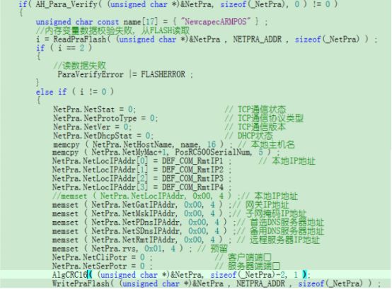
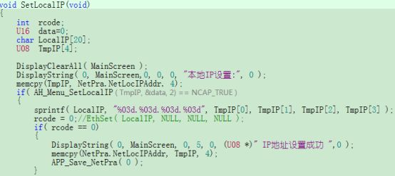
Take a look at the following two styles of code, which one you prefer.

Another style:

The same is to save the parameters, do you have to disassemble it into AlgCRC16, WritePraFlash( (unsigned char *)&NetPra, NETPRA_ADDR, sizeof(_NetPra) )?
There is also AH_Para_Verify, which is really redundant in the application layer. The detection fails and it is read from Flash. Regarding the parameters, the legitimacy should be checked as soon as the machine is turned on.

Since all parameters are to be saved, a package should be made, as shown in the figure above, to make a plan for the different parameters used by the system. The application layer calls APP_Open_UseFile or APP_Read_UseFile instead of reading and writing Flash directly.
Let’s take a look at the famous Android architecture of Google. Although it is very complicated, it looks like building blocks from the block diagram. Each functional module is independent and has a clear hierarchy. The lowest layer is based on the Linux Kernel, then the libraries of various component libraries, and then the application frameworks and applications.

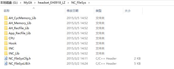
Take NC_FileLib, the file library module as an example, if you want to use it on other platforms, such as EH0918 handheld device, you only need to transplant a few hardware layer interfaces.

NC_FileSys file library, the hardware-related interface is in the Hook folder, and the following functions can be re-implemented: void HW_FRAM_Init( void )unsigned int HW_FRAM_Read( unsigned int addr,unsigned int size,unsigned char *buffer)unsigned int HW_FRAM_Write( unsigned int addr, unsigned int size, unsigned char *buffer )//Erase one page of FLASH (the smallest unit of FLASH erase) unsigned int HW_Flash_PageErase( unsigned int page )unsigned int HW_Flash_Read( unsigned int addr, unsigned int size, unsigned char * buffer )unsigned int HW_Flash_NotEraseWrite( unsigned int addr, unsigned int size, unsigned char *buffer )//Erase one page of FLASH (the smallest unit of FLASH erase) unsigned int HW_Flash_PageErase( unsigned int page)
According to the above modular design ideas, it is easy to realize a simulated pos machine:
Take the development of a smart POS application as an example: the functional modules involved in a smart POS include: read and write card functions, save and read consumption records, search and save blacklists, interface display, menu display, communication download parameter upload records, etc.
The functional modules used to realize a simulated POS on the computer include a file storage module, a card processing module, an algorithm module, and a UnionPay library module. I transplanted these modules to the computer.
It is just a functional realization, complete credit card consumption, record storage, record upload, blacklist, fare download and other functions. The interface is a Dos window. If you use QT to make the interface in the future, it will be a full-featured analog POS machine, but you have to pick up the C++++ that has been abandoned for many years. You can continue to improve to do a host computer simulation POS, change the compiler to run on the real POS after the host computer simulation debugging and cross-compilation.
Regarding the realization of the card processing module, since there is no card reader on the computer, an external card reader is used. Connect the serial port of the card reader to the computer. A card reader service is provided on the computer, and a card reader card interface with TCP interface is provided.
Transplant the file library, the embedded program is the flash for operation, and replace the interface used in the file library with the form of reading and writing files on the computer.
To transplant the algorithm library, the algorithm library is written in C, and you can directly recompile it on the windows platform with gcc.
Each functional module can be further subdivided into sub-modules.
Take the communication library as an example: embedded devices need to support a variety of different communication modules. For example, hardware devices include A701, A801, B502, etc., and communication modules include GL868, MG323, MC8630, N710, ZIGBEE, etc. These devices support all or part of the communication modules, respectively.
The overall structure is divided into the following:

The driver is roughly divided into three layers: 1. Interface layer: Provide users with a unified interface, such as: Connect, TxData, RxData, Disconnect, etc. 2. Driver layer: Expose a unified interface to the interface layer. These interfaces are used to complete the actual connection disconnection and data transmission and reception, such as DevConnect, DevTxData, RxData, Disconnect, etc. This layer is only related to the supported communication modules, and does not directly access any hardware functions, including serial communication and GPIO control, which are all implemented through the underlying device layer. 3. Device layer: Provide a unified interface to the driver layer. These interfaces implement communication with modules by accessing physical hardware, such as: XXXPowerOn, SerialSend, SerialReceive, etc., and define which modules the device supports.
For some commonly used functions of writing communication module drivers, a series of auxiliary functions are provided in the module to avoid duplication of work.
Disposable Pod,OEM Dispossble Vape,OEM Dispossble Electronics-cigarette Vape,OEM Vape Pod,OEM Vape Disposable Atomizer Pod
TSVAPE Wholesale/OEM/ODM , https://www.tsecigarette.com
