
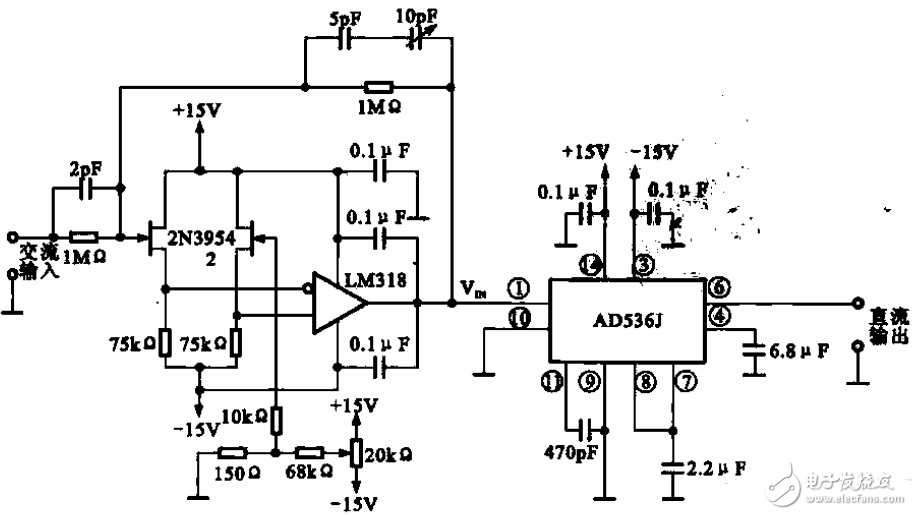
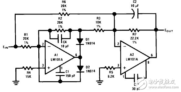
The AC-to-DC circuit is a circuit that converts a sinusoidal AC into a DC. If the input signal is not a sine wave, but a triangular wave or a sine wave with a large distortion, the relationship between the average value and the effective value is 1.11 times. The error will be relatively large. In this case, the average value is not converted, but is directly converted into an effective value that can be obtained for AC, and then converted into DC. The circle shows the AC RMS and DC conversion circuit, which is mainly used for signal measurement. In the device.
Display and its DC to AC converter. The display includes a tube and a DC to AC converter. The DC AC converter includes a pulse width modulation unit, a DC/DC conversion unit, and a self-oscillation circuit. The pulse width modulation unit is used to output a PWM signal, and the pulse width of the PWM signal is determined according to the level signal. The DC-DC conversion unit receives the first DC voltage and converts it to a second DC voltage, wherein the level of the second DC voltage is determined by the PWM signal. The self-oscillating circuit generates an alternating voltage to the lamp according to the second direct current voltage. The DC AC converter can determine the level of the output AC voltage through the level signal. When the DC AC converter operates in the burst mode, the level signal is interleaved high level and low level, so that the output AC voltage It is bursty.
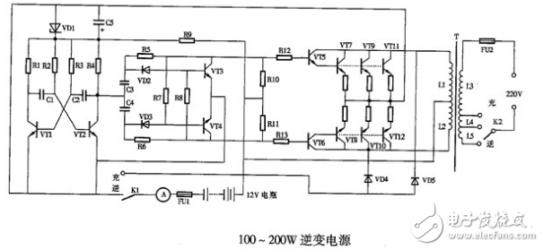
A circuit in which an inverter power source converts direct current into alternating current is called an inverter circuit. In a specific case, the same thyristor converter circuit can be used for both rectification and inverter. As shown below:
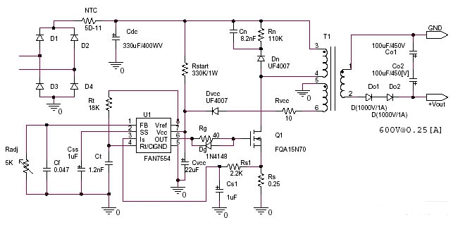
High voltage boost power supply circuit: AC 220V to DC 600V switching power supply circuit
specification:
Input voltage = 220Vac ± 10 % 50 / 60Hz
Output voltage = 0~600Vdc 0.25A
Switching frequency: 70~100kHz
Design Guide:
In DCM mode, the output power is 200 watts.
The rms current is degraded. The continuous current mode is calculated as:
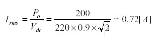
If the optimal operating duty is set to D = 0.35, then enter the peak current
Therefore, the voltage detection voltage level is limited to 1.5V from the FAN7554 data.
220V turn positive and negative 5V power supply circuit diagram
Positive and negative 5V power supply circuit Figure 78 and 79 series are positive voltage and negative voltage series voltage regulator integrated circuits, respectively, small size, high integration, linear adjustment rate and high load regulation rate, occupying a large market in the era of linear power supply. LM7805 is a fixed +5V output voltage regulator integrated circuit (special method can also make the output higher than 5V), the maximum output current is 1A, the standard package form has TO-220, TO-263. 78 and 79 series integrated circuit applications are relatively fixed The circuit form is simple, only the positive and negative DC voltage output should pay attention to the minimum output power and minimum output voltage of the transformer, as shown in Figure 1.
According to the principle of energy conservation, the input and output power of the power supply are equal under ideal conditions. In practice, considering the loss of copper loss and other components, the output power of the power supply is less than the input power. The 78 series and 79 series regulators have a DC voltage difference of 2 to 3V. Because it is a positive and negative dual power supply output, the DC voltage difference before and after voltage regulation should be 5 ~ 6V
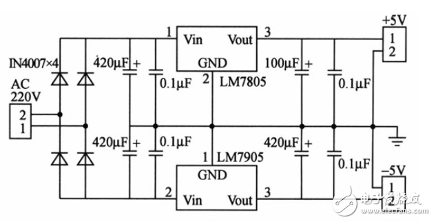
Figure 6. Positive and negative voltage output of the LM7805 and LM7905
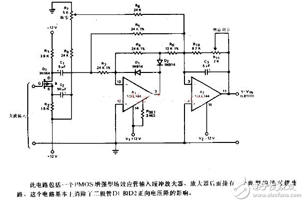
AC to DC circuit diagram (6)The precision AC-DC converter circuit is shown below:
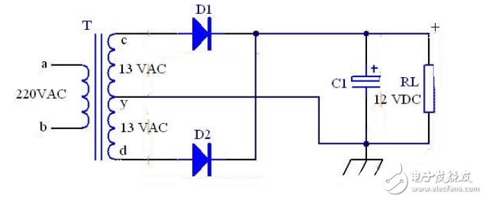
The following picture shows a 12V DC output power supply, which is commonly used in recorders, etc. T is a buck-type power transformer with a center-tap in the secondary winding. The primary windings a and b are connected to the input AC mains 220V, secondary winding. The number of turns between c and y is equal to the number of turns between d and y, so the induced voltage between c and y is equal to the induced voltage between d and y, and the output is about 13V AC, using a full-wave rectifier circuit. When c is the positive half cycle of AC, D1 is turned on and D2 is not turned on. When d is the positive half cycle of AC, D2 is turned on, D1 is not turned on, and the output ripple voltage is filtered by C-type on load RL. A DC voltage of 12V was obtained.
This circuit can also be changed to a half-wave rectification circuit, the transformer is redesigned, the secondary winding is designed as a single set of 13V, a rectifier is used, or the D1 or D2 in the above figure is cancelled, and the corresponding winding is not used, which becomes A half-wave rectifier circuit. It can also be changed to a full-bridge rectifier circuit. On a single 13V of the secondary winding of the transformer, four rectifiers or one rectifier bridge stack are used, which becomes a full-bridge rectifier circuit.
It is a kind of electric energy or signal transmission device, which is usually composed of several wires or groups of wires.
Power cord plug is also called power plug. It is used in various fields and countries. Power plug can be roughly divided into conversion power plug, injection power plug and assembly power plug. The general power plug can be used only by connecting the power cord. According to the different purposes of the power plug, the power cord plug can be used at the voltage of 250V, 125V and 36V. According to the different current, it can be used in 16a, 13a, 10a, 5A, 2.5A.
AC-DC Power Cord
ShenZhen Antenk Electronics Co,Ltd , https://www.antenk.com