
The final draft of the "Electrical Vehicle Conductive Charging Interoperability Standard" has been released, and the electric vehicle and charging pile industry will soon have a detailed test standard. Under the supervision of this test standard, the compatibility of electric vehicles and charging piles will be greatly improved. This article will analyze the interoperability test standards for AC piles.
First, the test system consists ofThe standard first mentioned the composition of the AC charging pile test system, as shown. It mainly includes vehicle controller analog box (test charging control process of AC charging pile, abnormal charging status and connection control timing, etc.), AC power (analog grid power supply characteristics), load (simulated battery consumption charging pile output energy), test instrument (Measure the electrical characteristics of the charging pile and the state of the control signal, etc.), the main control unit (control the vehicle controller analog box to simulate the different states of the charging process, and collect and record the test data generated by the test instrument to generate a test report). These parts of the orderly linkage test of the charging pile can greatly improve the testing efficiency.
Second, the charging control process testThe charging control process test of the AC charging post is divided into four phases: connection confirmation test, charge ready test, start and charge phase test, and normal charge end test. The detected contents include the detection point 1, the voltage value of the detection point 4, the frequency of the PWM signal, the rise time, the fall time, the state of charge, and the like.
The test objectives for each phase are
Connection confirmation test: Check whether the power supply device can judge the connection status between the power supply plug and the power supply socket through the voltage value of the detection point 1 or the detection point 4.
Charge Ready Test: Check if the power supply unit can detect that the vehicle is ready and initiate charging.
Start-up and charge phase test: During the charging process, check whether the power supply device can inform its maximum power supply capability through the duty cycle of the PWM signal.
Normal charging end test: Check if the charging device is normal when the vehicle stops receiving charging command.
Third, charging connection control timing testThe purpose of this test is to check whether the power supply device charging connection controls various state jumps and time intervals to meet the requirements. The state transition diagram is shown in the figure below. The charging connection timing of the power supply equipment during charging should meet the requirements specified in A.4 and A.5 of GB/T18487.1-2015.
Fourth, abnormal charging testIn this test requirement, many abnormal scenes that may be encountered at the charging site are specified, and it is detected whether the AC charging pile can stably and safely stop charging after encountering these abnormalities. The abnormal use cases for AC charging piles specifically include:
CC open circuit: Before charging and charging, when the power supply interface is disconnected, check whether the power supply device can stop charging.
CP grounding: During normal charging, ground the CP line with a 120Ω resistor, check the voltage at the detection point 1, the PWM signal, the K1 and K2 states, and the state of charge.
PE needle disconnection: Before charging and charging, simulate disconnecting the PE line for 5s, check the voltage of the detection point 1, the PWM signal, the state of the switch S2, and the state of charge.
Output overcurrent: During the charging process, the analog output current exceeds the maximum supply current of the device under test, and check whether the power supply device can stop charging.
Switch S2 is turned off: During the charging process, when switch S2 is turned off, it is checked whether the power supply device can stop charging and maintain the PWM output.
Five, loop voltage testThe test item is for the CP loop voltage test for the part of the AC charging pile. Before the charging, when the positive voltage of the detection point 1 is within the nominal value error range (8.2V~9.8V), the power supply equipment should be able to allow charging; During the process, when the positive voltage of the detection point 1 is within the nominal value error range (5.2V~6.8V), the power supply equipment should be able to charge normally; when the positive voltage of the detection point 1 exceeds the nominal value error range, the power supply equipment should be The connection failure is recognized within 50ms, and charging or stopping charging is not allowed.
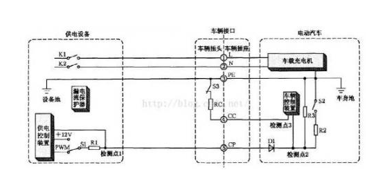
Figure 3 AC charging pile control guiding circuit diagram
Outdoor Fixed LED Display is a popular product for its high quality, every year sold to at least 80,000 pieces around the world, including Europe, North America, southeast Asia.Compared to other indoor LED display in the market, its biggest advantage is that it can display high-definition images while maintaining low power consumption.Besides, it adopts Die casting aluminum cabinet which is ultra-thin and ultra-light and owns good heat dissipation.Easy to install and maintain and suitable for multiple indoor scenes.
Application:
* Business Organizations:
Supermarket, large-scale shopping malls, star-rated hotels, travel agencies
* Financial Organizations:
Banks, insurance companies, post offices, hospital, schools
* Public Places:
Subway, airports, stations, parks, exhibition halls, stadiums, museums, commercial buildings, meeting rooms
* Entertainments:
Movie theaters, clubs, stages.
Outdoor Fixed LED Display,Led Wall Display Screen,Curved Led Display Screen,Led Display Board
Guangzhou Chengwen Photoelectric Technology co.,ltd , https://www.cwstagelight.com