
1 Introduction Inverter applications include steel, chemicals, automotive, machine tools, electrical machinery, food, paper, cement, mining, petroleum, factory buildings, and more. Through the setting and debugging of the function parameters of the inverter, the corresponding functions can be realized. Generally, there are dozens or even hundreds of parameters for the user to select. In practical applications, it is not necessary to set and debug each parameter. Use the factory settings. However, some parameters have a lot to do with the actual use, and some are also related to each other, so it should be set and debug according to the actual use. The good or bad commissioning of the inverter after installation determines the service life of the inverter, the application effect and the stability of the operation, etc. The final result is the size of the economic benefits of the enterprise. It is impossible to adjust the cost saved in one day. It is estimated that if the adjustment is not good, it may be a heavy loss. The following is a summary of the experience of the author in the use of general transmission inverters, hoping to provide reference to other users, so that the inverter can be better promoted and used in China, bringing greater economic benefits to Chinese enterprises.
2 Steps for commissioning the inverter The inverter can be successfully applied to various loads to obtain long-term stable operation. On-site commissioning is critical and must be carried out according to the corresponding steps.
2.1 Inspection of the inverter before no-load power-on (1) Connect the power input terminal of the inverter to the power supply through the leakage protection switch;
(2) Ground the ground terminal of the inverter;
(3) Confirm whether the voltage frequency level of the brand name tag of the inverter matches the grid, and send power after error;
(4) The main contactor is closed, the fan is running, and the input power supply voltage is tested in the standard specification with the multimeter ac file;
(5) Familiar with the operating keyboard keys of the inverter;
Take Pu Chuan as an example: fwd (forward run key: let the drive run in the forward direction), rev (reverse run key: let the drive run backwards), esc/displ (exit/display key: exit the data change of the function item, The fault status exits, exits the submenu or enters the status display menu by the function item menu), stop/reset (stop reset key: stop the drive, abnormal reset, fault confirmation), prg (parameter setting/shift key), set (Parameter setting key: Save the value after modification, change the monitoring target in the monitoring state), â–² (Parameter change/addition and subtraction keys: set value and parameter change use, change the given frequency in the monitor state), jog (jog operation) Key: Press the inching operation to release the stop operation. The definitions of the different inverter operation keys are basically the same.
(6) Run the inverter to 50hz, and test the three-phase output voltage balance of the inverter u, v, w;
(7) After the power failure is completely not displayed, connect the motor cable.
2.2 Inverter with motor no-load operation (1) Set the basic rated parameters of the motor, and comprehensively consider the operating current of the inverter.
(2) Set the maximum output frequency, fundamental frequency and set torque characteristics of the inverter. The v/f type selection includes items such as the highest frequency, base frequency, and torque type. The highest frequency is the highest frequency that the inverter-motor system can operate. Since the maximum frequency of the inverter itself may be high, when the maximum frequency allowed by the motor is lower than the highest frequency of the inverter, it should be set according to the requirements of the motor and its load. set. The basic frequency is the dividing line between the inverter for constant power control and constant torque control of the motor, which should be set according to the rated voltage of the motor. The torque type refers to whether the load is a constant torque load or a variable torque load. The user selects one of the types according to the v/f type map and load characteristics in the inverter's instruction manual. The general-purpose inverters are equipped with multiple v/f curves for the user to select. The user should select the appropriate v/f curve according to the nature of the load. In order to improve the low-speed performance of the inverter when starting, the torque output from the motor can meet the requirements of the production load start-up, and the starting torque should be adjusted. In the asynchronous motor variable frequency speed control system, the torque control is more complicated. In the low frequency band, since the influence of resistance and leakage reactance cannot be ignored, if the v/f is kept constant, the magnetic flux will decrease, thereby reducing the output torque of the motor. For this reason, the voltage is appropriately compensated at the low frequency band to increase the torque. Generally, the inverter is manually compensated by the user. The general transmission inverter provides users with two options: 42 v/f lifting modes and automatic torque boosting.
(3) The frequency setting and running control of the inverter are all keyboard mode. Press the running key and stop key to observe whether the motor can start and stop normally.
(4) Familiar with the protection code when the inverter runs fault, observe the factory value of the thermal protection relay, observe the setting value of the overload protection, and modify it if necessary. The user of the inverter can set the electronic thermal relay function of the inverter according to the instruction manual of the inverter. The threshold of an electronic thermal relay is defined as the ratio of the rated current of both the motor and the frequency converter, usually expressed as a percentage. When the output current of the inverter exceeds its allowable current, the overcurrent protection of the inverter will cut off the output of the inverter. Therefore, the maximum value of the threshold current of the inverter electronic thermal relay does not exceed the maximum allowable output current of the inverter.
(5) Run the inverter to full frequency, test the output voltage and current to see if it matches the value monitored by the keyboard.
2.3 Load test operation (1) Manually operate the operation stop button of the inverter panel, observe the motor running stop process and monitor the inverter to see if there is any abnormality.
(2) If the inverter has overcurrent protection during the start and stop of the motor, the acceleration and deceleration time should be reset. The acceleration of the motor during acceleration and deceleration depends on the acceleration torque, and the frequency change rate of the inverter during start and brake is set by the user. If the motor's moment of inertia or motor load changes, when the speed is increased or decelerated according to the preset frequency change rate, there may be insufficient acceleration torque, which may cause the motor to stall, that is, the motor speed is not in harmony with the inverter output frequency, resulting in Current or over voltage. Therefore, it is necessary to set the acceleration and deceleration time according to the motor inertia and load, so that the frequency change rate of the inverter can be coordinated with the motor speed change rate. The reason for checking whether this setting is reasonable is to first select the acceleration and deceleration time according to experience, and if there is overcurrent during the starting process, the acceleration time can be extended appropriately; if overcurrent occurs during braking, Prolong the deceleration time appropriately. On the other hand, the acceleration and deceleration time should not be set too long, and the long time will affect the production efficiency, especially in the operating conditions of frequent start and brake.
(3) If the inverter still has an operation fault, try to increase the protection value of the maximum current, but the protection cannot be canceled, and at least 10% to 20% of the protection margin should be left.
(4) If the inverter operation failure still occurs, replace the inverter with a larger power.
(5) If the inverter drives the motor to reach the preset speed during the startup process, there may be two cases:
â— The system generates mechanical resonance and can be judged from the sound of the motor running. By setting the frequency jump value, you can avoid the resonance point. Generally, the inverter can set three-level jump point. When the inverter controlled by v/f drives the asynchronous motor, the current and speed of the motor will oscillate in some frequency segments. In severe cases, the system cannot run, and even the overcurrent protection occurs during the acceleration process, so the motor cannot start normally. It is more serious when the light load or the moment of inertia is small. The common inverters are equipped with a frequency jump function. The user can set the jump point and the jump width on the v/f curve according to the frequency point at which the system oscillates. These frequency segments can be automatically skipped when the motor accelerates to ensure that the system can operate normally.
â— The torque output capability of the motor is not enough. The factory parameters of different brands of inverters are different. Under the same conditions, the load capacity is different. The load control capability of the motor may be different due to different inverter control methods. The output efficiency is different, resulting in different load capacity. In this case, the value of the torque boost amount can be increased. If it is not available, the manual torque boost function can be used. Do not set too large, and the temperature rise of the motor will increase. For fan and pump loads, the curve for the torque reduction should be reduced.
2.4 After the system debugging setup of the inverter and the host computer is completed, if there is a host computer in the system, connect the control line of the inverter directly to the control line of the host computer, and change the operation mode of the inverter to terminal control. According to the needs of the host computer system, set the range of the inverter receiving frequency signal terminal to 0~5v or 0~10v, and the response speed of the inverter to sample the analog frequency signal. If an additional monitoring head is required, select the monitoring amount of the analog output and adjust the range of the inverter output monitoring terminal.
3 The common function parameters of the inverter are different due to the functions of each type of inverter, and the names of the same function parameters are also inconsistent. For the convenience of description, this paper takes the basic parameter name of the general transmission as an example. Since the basic parameters are almost all types of frequency converters, it is completely possible to bypass the class.
3.1 Acceleration/deceleration time The acceleration time is the time required for the output frequency to rise from 0 to the maximum frequency. The deceleration time is the time required to fall from the maximum frequency to 0. The acceleration and deceleration time is usually determined by the frequency setting signal rising and falling. When the motor is accelerating, the rate of increase of the frequency setting must be limited to prevent overcurrent, and when decelerating, the rate of decrease is limited to prevent overvoltage.
Acceleration time setting requirement: Limit the acceleration current below the overcurrent capacity of the inverter, and do not cause the inverter to trip due to the over-speed. The main point of the deceleration time setting is to prevent the smoothing filter circuit from being too high and not to regenerate the overvoltage. The inverter is tripped. Acceleration and deceleration time can be calculated according to the load, but in the debugging, it is often set to set the long acceleration/deceleration time according to the load and experience. Observe the overcurrent and overvoltage alarm by starting and stopping the motor; then gradually set the acceleration/deceleration time. Shorten, the principle of no alarm occurs during operation, and repeat the operation several times to determine the optimal acceleration and deceleration time.
3.2 Torque boosting, also called torque compensation, is a method of artificially increasing the low frequency range v/f to compensate for the torque reduction at low speeds caused by the stator winding resistance of the motor. When set to automatic, the voltage during acceleration can be automatically increased to compensate for the starting torque, so that the motor accelerates smoothly. If manual compensation is used, a better curve can be selected by experiment depending on the load characteristics, especially the starting characteristics of the load. For variable torque loads, if the selection is improper, the output voltage will be too high at low speed, and the phenomenon of wasting electric energy may even occur when the motor is loaded with load and the current is large, and the speed is not going up.
3.3 Electronic thermal overload protection This function is set to protect the motor from overheating. It is the temperature rise of the motor calculated by the cpu in the inverter according to the running current value and frequency, thus performing overheat protection. This function is only applicable to the “one-for-one†occasion, and in the case of “one-to-oneâ€, a thermal relay should be added to each motor.
Electronic thermal protection set value (%) = [motor rated current (a) / inverter rated output current (a)] × 100%.
3.4 Frequency limit is the upper and lower limit amplitude of the inverter output frequency. The frequency limit is a protection function that prevents the device from malfunctioning or the external frequency setting signal source is faulty, causing the output frequency to be too high or too low to prevent damage to the device.
4 Frequently asked questions when debugging the inverter
4.1 External electromagnetic induction interference treatment method If there is interference source around the inverter, they will invade the inverter through the radiation or power line, causing the control circuit to malfunction, resulting in abnormal operation or shutdown, and even damage the inverter in severe cases. It is important to improve the anti-interference ability of the inverter itself. However, due to the limitation of the cost of the device, noise suppression measures are taken externally, and it is more reasonable and necessary to eliminate the interference source. The following measures are specific methods for implementing the “three noes†principle for noise interference.
(1) All the relays around the inverter and the control coil of the contactor should be equipped with absorption devices to prevent the surge voltage, such as rc absorbers;
(2) Minimize the wiring distance of the control loop and separate it from the main line;
(3) The circuit that specifies the shielded line must be carried out according to the regulations. If the line is long, a reasonable relay method should be adopted;
(4) The grounding terminal of the inverter should be carried out according to the regulations, and it cannot be mixed with electric welding and power grounding;
(5) A noise filter is installed at the input end of the inverter to avoid interference introduced by the power supply line.
The above is the "three noes" principle of not outputting interference, not transmitting interference, and not accepting interference.
4.2 Influence of the inverter on peripheral equipment and fault prevention The installation and use of the inverter will also affect other equipment. Therefore, it is necessary to study what measures should be taken.
(1) High-order harmonics of power supply Since most of the current inverters use the pwm control mode, high-order harmonic currents are generated on the power supply side, and the voltage waveform is distorted, which has a serious impact on the power supply system. The usual treatment measures are: The special transformer is used to supply power to the inverter, which is separated from other power supply systems; a filter reactor is installed on the input side of the inverter to reduce high-order harmonic components.
(2) For the case where there is a line capacitor, the high-order harmonic current will increase the capacitance current, causing serious heat generation. The reactor must be connected in series before the capacitor to reduce the harmonic component.
In addition, since the software development of the inverter is more perfect, various fault prevention measures can be set in the inverter in advance, and the fault can be maintained after the fault is resolved;
5 General transmission pi7000 In the application of the injection molding machine, the injection molding machine is a device that injects plastic fluid into the mold control after heating, melting, stirring and supercharging various plastics to complete the injection molding of the workpiece. Its process is basically the same, each process requires different pressures and flows, that is, the workpieces that are processed are not all working at maximum pressure or flow. In the traditional way, the pressure and flow rate are regulated by the pressure proportional valve and the flow proportional valve, and the oil pump motor operates at a constant speed, resulting in waste of electrical energy. If the frequency converter is used to adjust the speed of the oil pump motor, the pressure and flow demand can be met in real time, which is economical and practical. The relevant units have successfully used the injection molding machine modified by the general-purpose inverter to achieve significant economic benefits. Therefore, it is worthwhile to promote the energy saving of the injection molding machine with the inverter. According to the actual experience, the power saving rate after the transformation of the inverter for medium and small injection molding machines is generally 20% to 60%. The injection molding machine signal is generally the main controller flow valve or pressure valve output 0 ~ 1a DC signal, supplied to the inverter to control the inverter's output frequency, so as to achieve the purpose of adjusting the oil pressure according to the process needs, to achieve energy savings. Inverter—Select the special pi7000z series special inverter, which has strong overload capability and has dual feedback signal interface of flow and pressure. According to the requirements of injection molding process, double signal and superposition are used to control the motor speed of the main oil pump.
(1) The pi7000 injection molding machine series inverter has the control mode required by the injection molding machine. ◠If the injection valve flow valve or pressure valve output only has a 0~1a DC signal during control, the signal is directly connected to the control board i2 or v2 (positive Signal) and v3 (negative signal, gnd) port, the current signal is sampled by three series connected 1ω/2w resistors (r85 or r88) between control board i2 or v2 and v3, and the sampling voltage is supplied to cpu to control the output of the inverter. .
◠If the main controller of the injection molding machine outputs two 0~1a DC signals, the first signal is connected to the control board i2 (positive signal) and v3 (negative signal, gnd) port, and the second signal is connected to the control board v2 (positive Signal) and v3 (negative signal, gnd) port, the current signal is sampled by 3 series 1ω/2w resistors (r85 and r88) between control board i2/v2 and v3, and the sampling voltage is supplied to cpu to control the output of the inverter. .
(2) Inverter parameter setting When inputting 0~1a DC signal from v2 port: f04=1, f01 o 01=0.00v (v2 input minimum voltage), o 02=3.00v (v2 input maximum voltage);
When inputting 0~1a DC signal from i2 port: f04=2, f04 o 04=0.00ma (i2 input minimum current), o 05=20.00ma (i2 input maximum current);
When inputting two 0~1a DC signals from v2/i2 at the same time: f04=3, f01 o 01=0.00v (v2 input minimum voltage), o 02=3.00v (v2 input maximum voltage), f69 o 04= 0.00ma (v2 input minimum current), o 05=20.00ma (i2 input maximum current).
The specific connection is shown in the drawing.
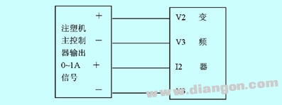
The injection molding machine and the inverter signal connection diagram
F09=2.0 (acceleration time 2s);
F10=2.0 (deceleration time 2s);
Other function parameters use default values.
6 In the actual use, the control circuit must be simple. At present, the application of the inverter on the injection molding machine is not only a simple operation mode of one inverter for one motor, but also a large-scale injection molding machine with multi-pump centralized control mode. Must pay attention to:
(1) To fully understand the technical performance, use requirements, internal functions of the selected inverter and give full play to its special features;
(2) To fully understand the process requirements, technical requirements, and application requirements of the equipment to be used, including loads;
(3) To fully understand the existing control circuit of the useful equipment, the function of the hydraulic oil circuit and various accessories is based on the principle of changing or minimizing the parts of the original equipment, how to skillfully obtain the control signal, and realize the existing The simplest combination of equipment and frequency converter is very important;
(4) The inverter sometimes causes harmonic interference to the temperature control of the injection molding machine. Some measures should be taken, such as ensuring that the equipment is well grounded. The input and output wires of the inverter are connected to the magnetic ring or after the high-frequency absorption capacitor is connected. Into; control measures for the injection molding machine to take isolation measures. Also consider factors such as the environment, ease of operation, and ease of maintenance. Briefly described as follows: the control of the injection molding machine uses a computer board (single-chip microcomputer), its pressure setting, timing setting can be artificially given according to the process conditions, using the output power value of the computer board to control the pressure proportional adjustment valve, thereby adjusting the main oil pump The size of the pressure. Its output is a linear current ma value, which is changed to 4~20ma through the current converter, directly connected to the inverter control input, thus changing the output frequency of the inverter, which also changes the speed of the main oil pump motor. Dual purpose of voltage regulation and power saving. Features of the control scheme: simple and reliable, no need to change the original circuit, convenient adjustment, and precise control.
The use of frequency converter to transform the injection molding machine, the commissioning is simple, has significant economic benefits, and is worth promoting.
7 Conclusion In the application debugging, the inverter must follow the steps of debugging, fully understand the function parameters of the inverter and set it well, fully understand the process requirements of the load, fully consider the site environment, prevent problems before they occur, and strive for one-time debugging success. It can stabilize long-term operation and avoid unnecessary losses.
A new rule from the Drug Enforcement Administration (DEA) threatens to upend the American hemp industry, and could even result in criminal prosecutions for manufacturers of CBD and delta-8 THC products.
The DEA says the [interim final rule," issued Aug. 20, is simply a matter of adjusting its own regulations to account for changes to the Controlled Substances Act that were mandated by the 2018 Farm Bill (or Agricultural Improvement Act) that legalized hemp and CBD production. The new rule [merely conforms DEA`s regulations to the statutory amendments to the CSA that have already taken effect," says the agency. The new rule doesn`t break any ground, according to the DEA.
But many experts on cannabis and hemp law say the DEA rule creates a potential pathway the law enforcement agency could use to prosecute hemp processors and producers of CBD (cannabidiol) and delta-8 THC (or Δ8THC) products. There are two issues: partially processed CBD, and [synthetically derived" delta-8 THC.
Cbd Pod System Oem,Cbd Vape Pod Oem,Best Cbd Pod System,Cbd Pod System
Shenzhen MASON VAP Technology Co., Ltd. , https://www.disposablevapepenfactory.com