
Wireless power transmission (WPT) refers to the transmission of energy between transmitting and receiving units. This technology is mainly used to wirelessly charge electronic devices such as mobile phones and electric cars. Although wireless energy transmission can bring many advantages, it still faces some problems that need to be solved urgently. At this time, you can use the power of simulation. For example, in some WPT technologies, the device must be placed in a specific orientation for effective charging. We will now analyze the effect of the direction on the functionality of the two WPT antennas.
Wireless energy transmission technologyIn our daily life, electronic devices are a very important part. Imagine that you don’t need wires or any cables to charge these devices. The development of wireless energy transfer technology (WPT) has made this possible. It provides a simple charging method for electrical equipment and supports the simultaneous charging of multiple devices. With the continuous development of technology, we have realized wireless charging in more and more areas, including electronic products from mobile phones to electric cars.
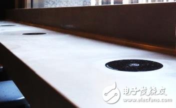
Figure 1, the coffee shop's wireless charging point.
As mentioned earlier, WPT technology can transfer energy without the use of solid wires or conductors, making energy ubiquitous. In general, we can transfer energy between two separate objects through electromagnetic fields. In this system, the energy transfer device (PTU) connected to the power supply generates a magnetic field that the energy receiving device (PRU) captures and converts it into usable energy.
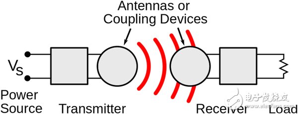
Figure 2. Simple example of wireless energy transmission. The PTU on the left and the PRU on the right.
For some WPT systems, the important point to consider is that the direction between the PTU and the PRU greatly affects the coupling of energy. Therefore, if you want to charge your device, you need to align it carefully with the PTU. But how much skew between PTU and PRU affects the coupling of energy?
Here, we will use simulation to analyze how the change in orientation will affect the wireless energy transmission antenna.
Analyze wireless energy transmission antennaIn today's wireless energy transmission tutorial, we will analyze the energy coupling between two circular loop antennas. The example antenna consists of a polytetrafluoroethylene (PTFE) wide plate and a thin layer of copper located on it, and simulates the thin layer of copper as a perfect electrical conductor (PEC). Each device contains a lumped inductor and a lumped port that can excite or terminate the antenna.
There is an UHF RFID tag inside the antenna that can operate at a frequency of 915 MHz. The shape itself supports inductive coupling.
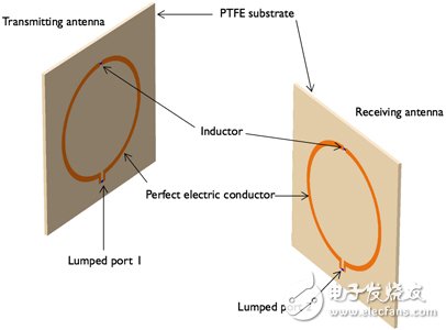
Figure 3, model geometry. Note that this does not include airspace and Perfect Matching Layer (PML).
In our simulation, the receiving antenna is rotating and the transmitting antenna is maintained in a fixed position. This setting is similar to the following scenario: The charger is fixed in position and the placement angle of the phone is adjusted.
By changing the orientation, we will be able to find out the effect of the location change on the energy coupling. In order to visualize this effect, we simulated the distribution of the electric field mode and the energy flow between the transmitting antenna and the receiving antenna (under different rotation angles).
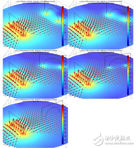
Figure 4. Electric mode and energy flow of wireless energy transmission antenna (arrow diagram).
The results show that when the antenna is placed face to face, that is, when the rotation angle of the receiving antenna is 0°, the electric field is strongly coupled, indicating successful wireless energy transmission. However, when the receiving antenna's rotation angle was 90°, we observed no distortion when the energy flow passed through the receiving antenna. At this angle of rotation, there is almost no coupling or effective coupling area. Therefore, we can conclude that the energy transmission between the two antennas is greatly reduced at this angle.
In the future, we can enhance the functionality of WPT antennas by developing systems that support working in multiple orientations. We will not need to pay attention to their specific placement when charging electronic devices.
Integrity and caring is the purpose of our service. Affordable, cost-effective, carefully selected materials, quality Seiko. On-demand customization, fast delivery, considerate service, honest cooperation. We have used oil in many physical factories, the manufacturers directly connect with customers, and have many years of industry experience. More high-quality materials to create high-quality products.
We specialize in the production of terminal blocks, there are different types, PCB Terminal Block and Din Rail Terminal Block. You can go to our website to browse. More Spring Terminal is on sale, which can be customized according to your needs. If you are interested, you can consult us. If you need some Terminal Pins or other Terminal Block Accessories, you can also consult us, we support customization and wholesale.

module terminal block,terminal block module,terminal block breakout module
Sichuan Xinlian electronic science and technology Company , https://www.sztmlchs.com