
Have you ever designed a power supply with a good load transient response under light load conditions? If so, and you also allow the power to be discontinuous, you may find that the gain of the control loop drops sharply under light load conditions. This results in a poor transient response and requires a large number of output filter capacitors. An easier way is to keep the power supply continuous under all load conditions.
Figure 1 is a simple synchronous buck converter that demonstrates the load transient response of continuous and non-continuous currents in the output inductor. The output inductor current remains continuous during load conditions as low as no load, because the synchronous rectifier allows the inductor current to flow in reverse under light load conditions. Simply replace the bottom FET (Q2) with a diode and the circuit can be turned discontinuous. Although this article describes the differences in buck topology, you will notice that all power supply topologies have similar responses.
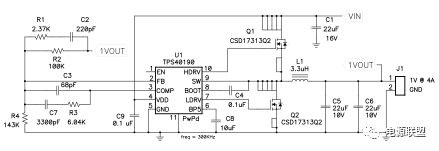
Figure 1 Simple buck converter for demonstrating transient response
Figure 2 shows two transient load responses for a 700mA step change in output current. The stitches on the left are continuous and the stitches on the right are non-continuous. In non-continuous situations, the transient response is more than three times worse than continuous. Synchronous FETs are used to force continuous operation. However, there are other ways to get a better transient response, including preloading the output or using a wobble inductor. Swing inductors are used to increase inductance at low currents. The achievement of this goal is mainly through two core materials: low current saturated high ferrite, and low current unsaturated powder ferrite.
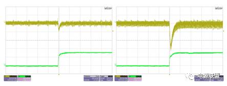
Figure 2 Synchronous operation (left) with optimal transient response
The reason for the poor transient response during discontinuous operation is that the loop characteristics change drastically, as shown in Figure 3. The curve on the left shows the loop gain during continuous operation. The control loop has a bandwidth of 50 kHz with a complementary angle of 60 degrees. The curve on the right is the response when the power stage is switched to discontinuous. The power stage changes from a pair of repolarizations during continuous operation to a single low frequency real pole during discontinuous operation. The frequency of this pole is determined by the output capacitor and the load resistor. Compared to the continuous case, you can see the phase shift process caused by the low frequency pole at low frequencies. At low frequencies, the gain drops sharply because the pole results in a lower crossover frequency, which reduces the transient response.
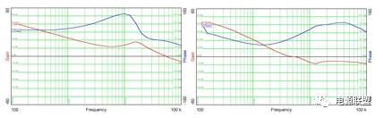
Figure 3 A large number of loop gains are lost in discontinuous operation (right)
In summary, synchronous rectification increases efficiency while also greatly aiding transient load regulation. It provides an efficient method for power preloading. In addition, it has a more stable control loop characteristics than the swing inductor. It improves the dynamics of traditional buck converters and all other topologies that can use synchronous rectification.
BAM Power Transmission Capacitors
BAM power transmission capacitors
RAM/RFM Induction Heating Capacitors,Water Pump Capacitor,Water Cooled Condense,Tank Capacitor
YANGZHOU POSITIONING TECH CO., LTD. , https://www.yzpst.com