
Electric vehicle power system
Xiaobian today tells you what is the electric vehicle power system. The name is controversial, which is the power system that drives the electric vehicle to drive and provide a continuous power source through external power. Before we understand the power system, let's first understand the electric car.
What is an electric car?
According to Baidu Encyclopedia, electric vehicles (also known as BEVs) refer to vehicles that use vehicle power as the driving force, drive the wheels with electric motors, and meet the requirements of road traffic and safety regulations. As the impact on the environment is relatively small compared to traditional cars, its prospects are widely optimistic, but the current technology is not mature.
Classification of electric vehicles
At present, the electric vehicles we see are mainly divided into three types, one is a pure electric vehicle (BEV), an electric vehicle driven entirely by a motor; the other is a hybrid electric vehicle (also called a composite electric vehicle PHEV), generally refers to It is an electric vehicle that uses electric oil and electricity to provide electric vehicle power source (that is, using both the internal combustion engine and the electric motor as power, and can be used separately); the last one is a fuel cell vehicle (FCEV), which uses a hydrogen-oxygen mixed fuel. Providing a power source can usually be “full charge†in a matter of minutes, because the supplemental fuel is hydrogen, combined with the kinetic energy of oxygen in the atmosphere to provide kinetic energy, providing a very low-carbon environmentally friendly power source.
Electric vehicle manufacturer
There are many electric vehicle manufacturers, and the application fields of electric vehicles are also very wide. At present, the most famous electric vehicle manufacturers mainly include Tesla, BYD, Toyota, Nissan, Chery, Chevrolet, Honda, BMW, Mitsubishi, Lexus and so on.
Tesla, as the United States focused on electric vehicles and energy companies, has been leading the industry in the development of electric vehicles since the launch of the first Roadster sports car in 2008. It has launched the Model S standard pure electric vehicle and the Model X luxury electric super. The running and upcoming Model 3 is one step ahead of the electric vehicle's automatic assisted driving technology.
The Internet car boom has also led the development of electric vehicles to a new high. In early January of this year, Faraday FF ​​and strategic partner LeTV officially launched the first production car exposure, and the 36-hour global reservation reached 64,124 units. Gree Group Dong Mingzhu recently acquired Zhuhai Yinlong New Energy and officially entered the Internet car. The goal is to clean, pure and environmentally friendly electric vehicles. It is not only the problem of electric vehicle power, but also the problem of electric vehicle energy storage.
Electric vehicle power system and its working principleThe following officially entered the topic, what is the electric vehicle power system? Here we first analyze the typical pure electric vehicle power system:
The basic structure of the electric vehicle power system is shown in the following figure. The electric drive subsystem is composed of an electronic control unit, a controller, an electric motor, a mechanical transmission device and a drive wheel. The main energy subsystem consists of a primary energy source, an energy management system, and a charging system. The auxiliary control subsystem has functions such as power steering, temperature control, and auxiliary power supply.
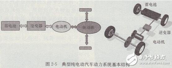
The electric drive and control system is the core of electric vehicles and the biggest difference from the internal combustion engine. The electric drive and control system consists of a drive motor, a power supply and a motor control unit. Other devices for electric vehicles are basically the same as those for internal combustion engines.
Pure electric vehicle power system working process:The power system works by controlling the motor to adjust the power flow between the motor and the power supply based on signals from the brake pedal and the accelerator pedal. The auxiliary power supply system mainly supplies power steering, air conditioning, braking and other auxiliary devices. In addition to inputting signals from the brake pedal and the accelerator pedal to the electric vehicle, the steering wheel input is also an important input signal, and the power steering system determines the car to flexibly depending on the angular position of the steering wheel.
Here is a brief introduction to the hybrid electric vehicle power system:According to the driving structure of the hybrid electric vehicle currently on the market, it can be mainly divided into three categories: series, parallel and hybrid.
(1) Series hybrid electric vehicle
The structural schematic diagram is as follows:
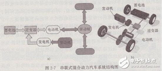
A series hybrid electric vehicle consists of three main components of an engine, a generator and a drive motor. The engine is only used to generate electricity, the electric energy generated by the generator is supplied to the electric motor, and the electric motor drives the car to travel. Part of the power generated by the generator charges the battery to extend the mileage of the hybrid electric vehicle. In addition, the battery can separately supply electric energy to the electric motor to drive the electric vehicle, so that the hybrid electric vehicle can run under zero pollution.
(2) Parallel hybrid electric vehicle
The structural schematic diagram is as follows:
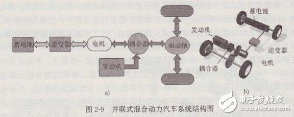
Parallel hybrid electric vehicles are mainly composed of two components of the engine and electric/generator. They are available in various combinations and can be selected according to the requirements of use. The power of the two powertrains can be superimposed on each other, and the engine power and electric/generator power are about 5-1 to 1 times the maximum driving power required by the electric vehicle, so that a low-power engine and an electric/generator can be used. The assembly size and quality of the entire power system are small, the cost is lower, and the stroke can be longer than that of the series hybrid electric vehicle, and its characteristics are closer to those of internal combustion engines. Parallel hybrid drive systems are typically 2-9a on small hybrid electric vehicles.
(3) Hybrid hybrid electric vehicle
The structural schematic diagram is as follows:
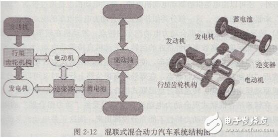
The hybrid hybrid electric vehicle combines the structural components of the series and parallel hybrid electric vehicles, and is mainly composed of three major powertrains: engine, generator and drive motor. The engine is basically kept stable and efficient, energy-saving operation, generator and battery supply drive motor power to drive electric vehicles.
Here are a few electric vehicle power system solutions:
The electric vehicle is driven by a lithium battery as the main power, and its high energy density advantage and stable dynamic performance are the primary conditions. The importance of the battery management system BMS is also self-evident. BMS is the core technology of the power battery pack and the key link of the electric vehicle.
At present, the battery management system has two management modes, namely, active equalization and passive equalization.
The two management modes have their own advantages and disadvantages. The methods used are generally to collect the cell voltage, the series current, and the temperature and the voltage of the battery pack. Then, these signals are transmitted to the arithmetic module for processing and issuing instructions, and finally the entire process is processed. The information command is transmitted to the car central control unit or the vehicle VMS system via the CAN communication system.
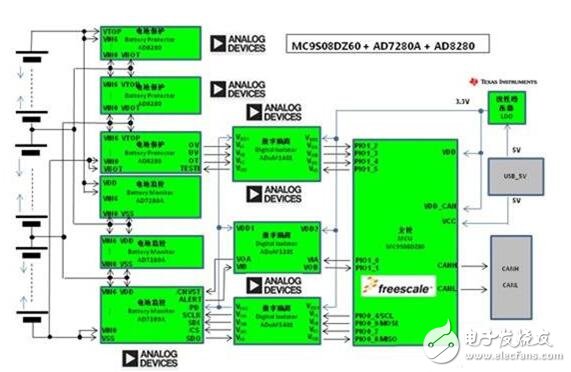
(I) ADI fully isolated lithium-ion battery monitoring and protection system
1. Features of the program
Lithium-ion battery packs contain a large number of battery cells that must be properly monitored to improve battery efficiency and extend battery life for safety. The 6-channel AD7280A device in the solution acts as the primary monitor, providing accurate voltage measurement data to the system demonstration platform evaluation board, while the 6-channel AD8280 device acts as a secondary monitor and protection system.
The AD8280 is a pure hardwired safety monitor for Li-Ion battery packs that, when used with the AD7280A, provides a low-cost, redundant, battery-backed monitor with adjustable threshold detection and shared or separate alarm outputs. It has a self-test function and is therefore suitable for high-reliability applications such as hybrid electric vehicles or high-voltage industrial applications such as uninterruptible power supplies. Both the AD7280A and AD8280 receive power from the monitored battery cells.
The ADuM5404 integrates a DC-DC converter to power the high-voltage side of the ADuM1201 and ADuM1401 isolators and VDRIVE power to the AD7280ASPI interface. These 4-channel, magnetically isolated circuits are a safe, reliable, and easy-to-use optocoupler replacement solution.
2. Scheme block diagram
3. Chip parameters
3.1 ADI AD7280A Parameters
Single processing 4-6 s front end
12 Bit ADC sampling with an average sampling time of 1 us per channel
Ability to monitor voltage and temperature of 6 channels, typically
Accuracy of ±1.6 mV (typical)
Multiple AD7280As can be daisy-chained, a single circuit
The board can monitor up to 48 battery cells with a conversion of only 7 μs
Provides passive battery cell balance control
Less than 6 mA in conversion mode
Power consumption is less than 1.8 uA in power down mode
SPI communication provides CRC verification to ensure data reliability
3.2 ADI AD8280 Parameters
Voltage range: 6.0 V–30 V
Multiple inputs monitor 3-6 battery voltages and 2 temperatures
Adjustable monitoring threshold: overvoltage, undervoltage, overtemperature
Alarm option: separate or shared alarm
Can be daisy-chained
(2) Infineon AUDO MAX product line
Today, high-performance microcontroller-based high-efficiency FOC systems create the conditions for safe and efficient solutions for electric and hybrid vehicle drives.
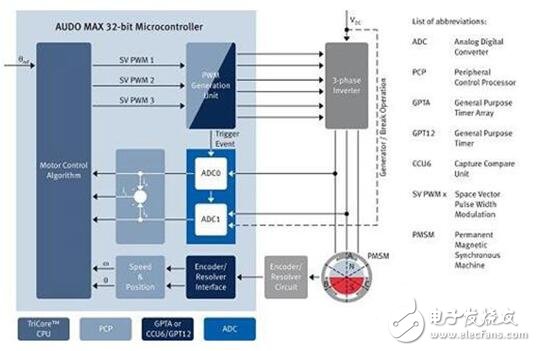
Figure 1: 32-bit TriCore microcontroller running in FOC mode
The Infineon AUDO MAX series is ideal for motor control. TriCore architecture and MC-ISAR eMotor drivers can control multiple three-phase motors with advanced control strategies, including brushless DC motor (BLDC) block swap (block commutaTIon, BC) and permanent magnet synchronous motor (PMSM) field oriented control (FOC) ). A single microcontroller can even support both BLDC and PMSM motor control. Compared to other types of motors, FOC-controlled PMSM motors offer higher energy efficiency, lower wear and precise control and positioning. In particular, this motor supports linear torque control and lays the foundation for its use in hybrid electric vehicle powertrain systems.
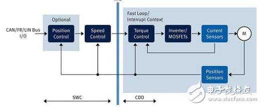
Figure 2: Current Control Loop in Motor Control
Figure 2 shows the current control loop for the MC-ISAR eMotor driver and the complex device driver (CDD) on the right. This time critical current control loop is processed in the interrupt context with a processing time of no more than 50 microseconds. On the left is an additional software component (SWC) for position and speed control, provided by the application.
Infineon's AUDO MAX series and MC-ISAR eMotor drives control up to four PMSM or BLDC motors in parallel while meeting the performance required for application task control. The MC-ISAR eMotor and the standard AUTOSAR MCAL driver are integrated by the same configuration tool, so users can configure microcontroller resources for the AUTOSAR MCAL and MC-ISAR eMotor drivers in the same interface, creating the conditions for seamlessly configuring different software modules. Automotive ECU developers can focus on application-related control of the motor without having to adapt the motor's control algorithms. To reduce system cost, the AUDO MAX series also supports direct resolver mode, eliminating the need for a rotary transformer IC. The AUDO MAX series and MC-ISAR eMotor drivers are designed to support safety applications.
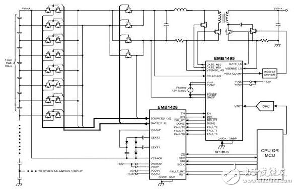
(3) TI introduces battery active balanced load technology
1. Features of the program
TI recommends the active equalization method adopted by electric vehicles: each battery cell controls the combination of transformer and charging circuit by matrix switch to form a function of voltage/current reservoir with adjustment function. When the battery core is charged and discharged multiple times After the inconsistency, the charge and discharge capacity of the whole battery is reduced. It can be adjusted by connecting the circuit of the back end to the reservoir. When charging, the battery will not stop charging due to monitoring the internal pressure of a certain battery core. It can completely release 100% of energy, thus extending the driving distance of electric vehicles.
TI's energy conversion efficiency of isolated DC-DC active equalization technology is as high as 87%. The EM1410 chipset consists of five core chips plus five power supply chips. The most important EMB1432 is a four-channel AFE chip, the EMB1428 is a seven-channel gate controller chip, and the EMB1499 is a seven-channel voltage control chip. To construct a four-channel bidirectional active cell balancing function, 14 cells in series and a maximum operating voltage of 60V, providing 5V bidirectional equalization voltage and maximum 750V stack output voltage capability, and meeting AECQ-100 automotive electronic verification standards.
2. Chip parameters:
2.1 EMB1432Q
Single processing 14S front end simulation
The highest input withstand voltage 60V
Output voltage error is +/- 1mV
SPI communication support 1MHz
Compliance with ACE-Q100 automotive specifications
2.2 EMB1428Q
The highest input withstand voltage 60V
SPI communication support 1MHz
Minimum standby power consumption (<100uA)
Compliance with ACE-Q100 automotive specifications
2.3 EMB1499Q
The highest input withstand voltage 60V
SPI communication support 1MHz
Minimum standby power consumption (<30uA)
Compliance with ACE-Q100 automotive specifications
For Huawei Glass,Huawei Honor Oca Glass,Lcd Screen Glass With Oca,Optical Clear Adhesive Glass
Dongguan Jili Electronic Technology Co., Ltd. , https://www.jltouch.com