
1 Introduction In the conventional system of variable frequency regulation composed of general-purpose inverter, asynchronous motor and mechanical load, when the position of the motor can be driven down, the motor will be in the regenerative braking state; or when the motor goes from high speed to low speed ( When the vehicle is decelerated, the frequency can be abruptly reduced. However, due to the mechanical inertia of the motor, the motor may be in a regenerative state. The mechanical energy stored in the transmission system is converted into electric energy by the motor and sent back to the six freewheeling diodes of the inverter. In the DC circuit of the inverter. The inverter at this time is in a rectified state. At this time, if no energy consumption measures are taken in the inverter, this part of the energy will cause the voltage of the energy storage capacitor of the intermediate circuit to rise. If the brake is too fast or the mechanical load is a hoist, this part of the energy may damage the inverter, so we should consider this part of the energy.
In the general-purpose inverter, there are two kinds of processing methods most commonly used for regenerative energy: (1) Dissipated into the "brake resistor" artificially connected in parallel with the capacitor in the DC loop, which is called the energy-consuming braking state; (2) When it is fed back to the grid, it is called the feedback braking state (also called the regenerative braking state). There is also a braking method, that is, DC braking, which can be used for situations requiring accurate parking or irregular rotation of the brake motor due to external factors before starting.
There are many experts in books and publications who have talked about the design and application of inverter braking, especially in recent times there have been many articles about "energy feedback braking". Today, the author provides a new type of braking method, which has the advantages of four-quadrant operation of "feedback braking" and high operating efficiency. It also has the advantages of "energy braking", no pollution to the power grid and high reliability.
2 Energy Braking The method of absorbing the regenerative energy of the motor by the braking resistor set in the DC loop is called energy braking, as shown in Figure 1.
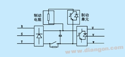
Figure 1 Energy consumption production schematic diagram has the advantages of simple structure; no pollution to the power grid (compared with the feedback mechanism), low cost; the disadvantage is low operating efficiency, especially when it is frequently braked, it will consume a lot of energy, and brake The capacity of the resistor will increase.
Generally, in the general-purpose inverter, the low-power inverter (below 22kW) has a built-in brake unit, and only needs to apply a brake resistor. For high-power inverters (above 22kW), external brake units and brake resistors are required.
3 Feedback braking to achieve energy feedback braking requires voltage equal-frequency control, feedback current control and other conditions. It adopts active inverter technology to invert the regenerative electric energy into an AC power returning grid with the same frequency as the grid, so as to realize the braking as shown in Fig. 2.
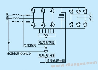
Figure 2 feedback grid production schematic
The advantage of feedback braking is that it can achieve four-quadrant operation. As shown in Figure 3, power feedback improves the efficiency of the system. The disadvantages are: (1) This feedback braking method can only be used under stable grid voltages that are less prone to failure (grid voltage fluctuations are not more than 10%). Because the grid voltage fault time is greater than 2ms during the generator braking operation, commutation failure may occur and the device may be damaged. (2) Harmonic pollution to the power grid during feedback. (3) The control is complicated and the cost is high.
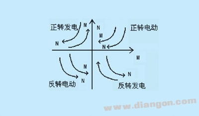
Figure 3 Four quadrant motion map
4 new braking method (capacitive feedback braking)
4.1 Main Circuit Principle The main circuit schematic is shown in Figure 4.
The rectification part is rectified by an ordinary uncontrolled rectifier bridge (composed of VD1-VD6 in the figure), the filter circuit uses a common electrolytic capacitor (C1, C2), and the delay loop adopts a contactor or a thyristor (T1). . The charging and feedback loop consists of the power module IGBT (VT1, VT2), the charging, the feedback reactor L and the large electrolytic capacitor C (capacity is about a few tenths of a farad, which can be determined according to the operating system of the inverter). The inverter part consists of the power module IGBT (VT5-VT10). The protection circuit consists of an IGBT and a power resistor.
(1) Motor power generation operating status
The CPU monitors the input AC voltage and the DC link voltage Ud in real time to determine whether to send a charging signal to VT1. Once Ud is higher than the DC voltage value corresponding to the input AC voltage (such as 380VAC-530VDC), the CPU is turned off. VT3, the charging process of the electrolytic capacitor C is realized by the pulse conduction of VT1. At this time, the reactor L and the electrolytic capacitor C are divided, thereby ensuring that the electrolytic capacitor C operates within a safe range. When the voltage on the electrolytic capacitor C reaches a dangerous value (for example, 370V), and the system is still in the power generation state, and the electric energy is continuously sent back to the DC loop through the inverter part, the safety circuit functions to realize the energy consumption braking (resistance system) Move), control the turn-off and turn-on of VT3, so that the resistor R consumes excess energy, which is generally not the case.
(2) Electric motor running state When the CPU finds that the system is no longer charging, it will pulse the VT3, so that the reactor L will become an instantaneous left-right and negative voltage (as shown in Figure 4), plus The voltage on the electrolytic capacitor C can realize the energy feedback process from the capacitor to the DC loop. By detecting the voltage on the electrolytic capacitor C and the voltage of the DC link, the CPU controls the switching frequency and duty ratio of the VT3 to control the feedback current to ensure that the DC link voltage Ud does not appear too high.
4.2 system difficulties
(1) Selection of reactor
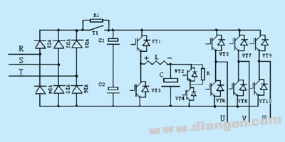
Figure 4 Schematic diagram of the capacitive feedback brake main circuit
(a) Considering the particularity of the working conditions, it is assumed that some fault occurs in the system, causing the position load of the motor to freely accelerate and fall. At this time, the motor is in a power generating state, and the regenerative energy is sent back through 6 freewheeling diodes. To the DC loop, causing the rise, the inverter is quickly charged, and the current will be large. Therefore, the diameter of the selected reactor should be large enough to pass the current at this time.
(b) In the feedback loop, in order to release the electrolytic capacitor as much energy as possible before the next charge, it is not possible to select a common iron core (silicon steel sheet), preferably made of ferrite material. Iron core, then look at the current value of the above considerations, it can be seen how big this iron core, I do not know whether there is such a large ferrite core on the market, even if there is, its price will certainly not be very low.
Therefore, I recommend using a reactor for each of the charging and feedback loops.
2) Difficulties in control
(a) In the DC circuit of the inverter, the voltage U 4 is generally higher than 500 VDC, and the withstand voltage of the electrolytic capacitor C is only 400 VDC. It can be seen that the control of this charging process is not like the control method of energy braking (resistance braking). It is. The instantaneous voltage drop generated on the reactor is ![]() The instantaneous charging voltage of electrolytic capacitor C is U 4 =U C -U L. In order to ensure that the electrolytic capacitor works within the safe range (≤400V), it is necessary to effectively control the voltage drop U L on the reactor and the voltage drop U L depends on The instantaneous rate of change in inductance and current.
The instantaneous charging voltage of electrolytic capacitor C is U 4 =U C -U L. In order to ensure that the electrolytic capacitor works within the safe range (≤400V), it is necessary to effectively control the voltage drop U L on the reactor and the voltage drop U L depends on The instantaneous rate of change in inductance and current.
(b) During the feedback process, it is necessary to prevent the electric current discharged from the electrolytic capacitor C from passing through the reactor to cause the DC link voltage to be too high, so that the system is overvoltage protected. 4.3 The main application and application examples are due to the superiority of this new type of braking method (capacitor feedback braking) of the frequency converter. Recently, many users have combined with the characteristics of their equipment and have proposed to equip this. Kind of system. Because of the technical difficulty, foreign countries still do not know whether there is such a brake method? At present, only Shandong Fengguang Electronics Co., Ltd. has switched from the inverter with the feedback braking method (there are still two in normal operation) to the new series of mine hoisting machines with capacitive feedback braking. So far, this A kind of capacitor feedback brake inverter is running normally in the Ningyang Security Coal Mine in Shandong and Taiyuan in Shanxi, filling the gap in China.
A manual pulse generator (MPG) is a device normally associated with computer numerically controlled machinery or other devices involved in positioning. It usually consists of a rotating knob that generates electrical pulses that are sent to an equipment controller. The controller will then move the piece of equipment a predetermined distance for each pulse.
The CNC handheld controller MPG Pendant with x1, x10, x100 selectable. It is equipped with our popular machined MPG unit, 4,5,6 axis and scale selector, emergency stop and reset button.
Manual Pulse Generator,Handwheel MPG CNC,Electric Pulse Generator,Signal Pulse Generator
Jilin Lander Intelligent Technology Co., Ltd , https://www.jllandertech.com