
The LTC4054 is a lithium battery charging chip from Linear Technology, a monolithic integrated chip designed to charge a single-cell lithium battery. The charger designed with the LTC4054 requires only a few components and is very compact. LTCA054 can charge the battery with high current without special heat sink, and it can take power from USB port. It is very suitable for peripheral devices such as MP3, PDA, digital recorder, etc. .
The LTCA054 is a complete single-cell Li-Ion battery constant current/constant voltage linear charger with ultra-small package of ThinSOT and minimal external components, making the LTC4054 ideal for portable devices. In addition, the LTC4054 can operate from USB power. Built-in MOSFET without sensing resistor and isolation diode; in high power operation and high ambient temperature, temperature compensation can limit charging current to prevent temperature abnormality; charging voltage is set at 4.2V, charging current can be controlled by a single external resistor; When the final float voltage is 4.2V and the charge current drops to 1/10 of the set value, the LTC4054 automatically stops the charge cycle; when the input power (wall adapter or USB power) is interrupted, the LTCA054 automatically enters the ultra-low current state. The battery current consumption is less than 2μA, and the power supply current drops to 25μA after the LTC4054 enters the off state.
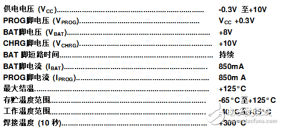
Maximum rating
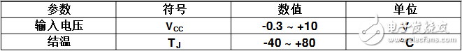
The scope of work
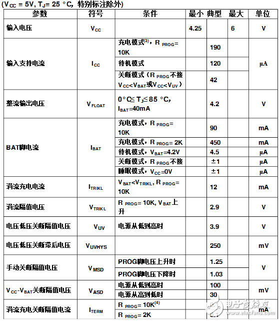
DC electrical characteristics
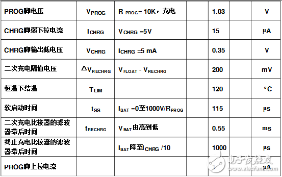
Note 1: Exceeding the maximum rating may cause loss of the chip.
Note 2: The chip does not guarantee normal operation beyond this working range.
Note 3: The support current includes the PROG pin current (approximately 100μA), but does not include the current flowing through the BAT pin to the battery (approximately 100mA).
Note 4: ITERM is part of the PROG pin resistance setting charge current value.
LTC4054 FeaturesProgrammable charging current up to 800mA;
No external MOSFET, sense resistor and isolation diode are required;
Ultra-small ThinSOT package, complete for single-cell Li-Ion battery charge management chip;
Constant current/constant voltage charging mode with temperature controlled maximum charging rate;
Single-cell Li-Ion battery can be charged directly from the USB interface;
Preset 4.2V charging voltage with an accuracy of ±1%;
Charging current monitoring output;
Automatic recharge; charge status output pin;
C/10 charge termination control;
Only 25 belly power supply current when turned off;
Turbulent precharge below 2.9V (LTC4054);
The trickle precharge function is invalid (LTC4054X);
Soft start to limit the inrush current.
Pin Diagram and Pin Function Description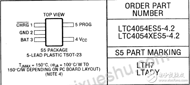
CHRG: (pin end 1) open-circuit charge state output. When the battery is charging, the CHRG pin is asserted low by the N-channel MOSFET. When the battery is fully charged, there is approximately 20μA through CHRG to indicate that the power supply is still present. When the LTC4054 detects an undervoltage lockout, CHRG is forced to a high impedance state.
GND: (Pin end 2) ground.
BAT: (Pin end 3) Charge current output, providing charge current to the battery and controlling the final float voltage to 4.2V. This voltage is set by a built-in precision resistor divider at this pin end and is disconnected in the semi-closed mode.
Vcc: (Pin end 4) power supply terminal, providing power to the charging chip Vcc range of 4.25V to 6.5V, need to connect at least 1μF filter capacitor. When Vcc is reduced to only 30mV above the BAT terminal, the LTC4054 enters the off state and the Ibat current is less than 2μA.
PROG: (Pin end 5) Charge current programming, control current monitor and half-closed pin terminals. The charging current is determined by the 1% resistor (Rprog) of this pin and ground. This pin is 1V when charging in constant current mode. In all modes, the voltage on this pin can be used to determine the battery charging current, Ibat = (Vprog / Rprog) * 1000, this pin is often used to turn off the charger. Disconnect the ground resistance from this pin, allowing 3μA to be pulled up. When it reaches the 1.21V limit shutdown voltage, the charger enters shutdown mode, charging stops and the input supply current drops to 25μA. The voltage at this pin is approximately 2.4V. This pin can output up to 1.5mA current. Reconnecting the ground resistance (Rprog) will return the charger to normal operation.
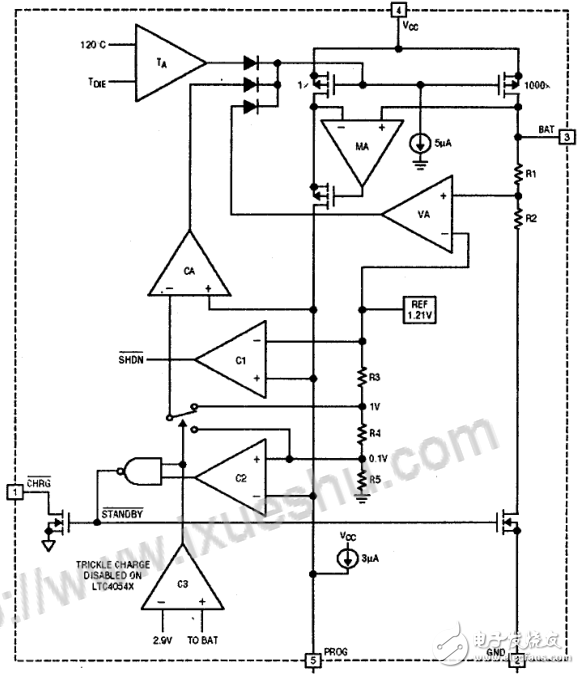
Internal functional block diagram
Car Phone Holder,Mobile Holder For Cars,Mobile Phone Holder For Dashboard,Mobile Phone Holder For Car Dashboard
Ningbo Luke Automotive Supplies Ltd. , https://www.car-phone-holder.com