
TI's TIDA-01425 is an automotive gateway reference design with Ethernet and CAN based on the DRA710 infotainment application processor with 100BASE-T1 automotive Ethernet, 100BASE-TX and CAN PHYs that can be cold-started, rushed and smashed Work in load, etc., reduce EMI power level and battery reverse protection, increase bandwidth and gateway processing power, mainly used in application processor modules, automotive gateways, construction equipment control units, free space sensors, rail transport motor control and vehicles Occupant detection sensor. This article describes the main features and block diagram of the DRA710 infotainment application processor, the main features of the automotive gateway reference design TIDA-01425, block diagram, circuit diagram, bill of materials and PCB design.
The DRA71x processor is offered in a 538-ball, 17&TImes;17-mm, 0.65-mm ball pitch (0.8mm spacing rules canbe used on signals) with Via ChannelTM Array (VCA) technology, ball grid array (BGA) package. The architecture is designed to deliver high-performance concurrencies for automotive applications in acost-effective solution, providing full scalability from the DRA75x ("Jacinto 6 EP" and "Jacinto 6 Ex"), DRA74x "Jacinto 6" and DRA72x "Jacinto 6 Eco " family of infotainment processors, including graphics, voice, HMI, multimedia and smartphone projection mode capabilities.
Programmability is provided by a single-core ARM Cortex-A15 RISC CPU with NeonTM extensions and aTI C66x VLIW floating-point DSP core. The ARM processor lets developers keep control functionsseparate from other algorithms programmed on the DSP and coprocessors, thus reducing the complexityof The system software.
Additionally, TI provides a complete set of development tools for the ARM, and DSP, including Ccompilers and a debugging interface for visibility into source code execution. The DRA71x Jacinto 6 Entry processor family is qualified according to the AEC-Q100 standard. The device features a simplified power supply rail mapping which enables lower cost PMIC solutions.
Main features of DRA710:
• Architecture Designed for InfotainmentApplications
• Video, Image, and Graphics Processing Support
– Full-HD Video (1920 × 1080p, 60 fps)
– Multiple Video Input and Video Output
– 2D and 3D Graphics
• ARM® Cortex®-A15 Microprocessor Subsystem
• C66x Floating-Point VLIW DSP
– Fully Object-Code Compatible With C67x and C64x+
– Up to Thirty-two 16 × 16-Bit Fixed-PointMultiplies per Cycle
• Up to 512KB of On-Chip L3 RAM
• Level 3 (L3) and Level 4 (L4) Interconnects
• DDR3/DDR3L Memory Interface (EMIF) Module
– Supports up to DDR-1333 (667 MHz)
– Up to 2GB Across Single Chip Select
• Dual ARM® Cortex®-M4 Image Processing Units (IPU)
• IVA-HD Subsystem
• Display Subsystem
– Display Controller With DMA Engine and up toThree Pipelines
– HDMITM Encoder: HDMI 1.4a and DVI 1.0Compliant
• 2D-Graphics Accelerator (BB2D) Subsystem
– VivanteTM GC320 Core
• Video Processing Engine (VPE)
• Single-Core PowerVR® SGX544 3D GPU
• One Video Input Port (VIP) Module
– Support for up to Four Multiplexed Input Ports
• General-Purpose Memory Controller (GPMC)
• Enhanced Direct Memory Access (EDMA) Controller
• 2-Port Gigabit Ethernet (GMAC)
– Up to Two External Ports
• Sixteen 32-Bit General-Purpose Timers
• 32-Bit MPU Watchdog Timer
• Six High-Speed ​​Inter-Integrated Circuit (I2C) Ports
• HDQTM/1-Wire® Interface
• Ten Configurable UART/IrDA/CIR Modules
• Four Multichannel Serial Peripheral Interfaces (McSPI)
• Quad SPI Interface (QSPI)
• Media Local Bus Subsystem (MLBSS)
• Eight Multichannel Audio Serial Port (McASP)Modules
• SuperSpeed ​​USB 3.0 Dual-Role Device
• High-Speed ​​USB 2.0 Dual-Role Device
• High-Speed ​​USB 2.0 On-The-Go
• Four MultiMedia Card/Secure Digital/Secure DigitalInput Output Interfaces (MMC/SD/SDIO)
• PCI Express® 3.0 Subsystems With Two 5-Gbps Lanes
– One 2-lane Gen2-Compliant Port
– or Two 1-lane Gen2-Compliant Ports
• Dual Controller Area Network (DCAN) Modules
– CAN 2.0B Protocol
• MIPI® CSI-2 Camera Serial Interface
• Up to 186 General-Purpose I/O (GPIO) Pins
• Power, Reset, and Clock Management
• On-Chip Debug With CTools Technology
• 28-nm CMOS Technology
• 17 mm × 17 mm, 0.65-mm Pitch, 538-Pin BGA (CBD)
DRA710 application:
• Human-Machine Interface (HMI)
• Navigation
• Digital and Analog Radio
• Multimedia Playback
• Automotive Display Audio Systems
• Automotive Entry Navigation and MultimediaSystems
• Automotive Digital Cluster Systems
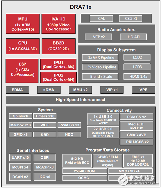
Figure 1. Block diagram of DRA710
Ethernet and CAN Automotive Gateway Reference Design TIDA-01425
The design implements Ethernet physical layer transceivers (PHYs) for increased bandwidth along with an automotive processor for greater processing capabilities allowing automotive gateways to pass More, the design offers a starting point for a full automotive gateway design with a full power tree, CAN PHYs, and components selected with automotive requirements and emission specifications in mind to simplify the design process.
The design implements Ethernet PHYs for increased bandwidthalong with an automotive processor for greater processing capabilities. The design offers anexcellent starting point for a full automotive. The design implements Ethernet PHYs for increased bandwidthalong with an automotive processor for greater processing capabilities. Gateway design. All components were selected based on automotive requirements and emission specifications in mind. The TIDA-01425 implements four total PHYs: two ethernet PHYs and two controller area network (CAN) PHYs. A 100BASE-T1 PHY allows forEthernet communication over a single twisted -pair cable, which lowers the wiring weight within the vehiclewhile also boosting overall bandwidth (100 Mb/s). Along with the single 100BASE-T1 PHY, a 100BASE-TXPHY is utilized to allow for diagnostic readings from the various electronic systems of a In addition to the Ethernet PHYs, two CAN PHYs allow for communication to CAN buses within the automo Bile.
Finally, the automotive processor allows for faster processing speeds to keep up with the increased bandwidth and also offers software scalability. further, through software, the processor can improveoverall vehicle security.
Reference design TIDA-01425 main features:
Processor based system
100BASE-T1 automotive ethernet
100BASE-TX and CAN PHYs
Operates off automotive battery
Designed to operate through cold crank, jump start, and load dump
Reduced EMI power stages
Reverse battery protection
Reference Design TIDA-01425 Application:
Applications Processor Module
Automotive Gateway
Control Units for Construction Equipment
Free Space Sensor
Motor Control for Rail Transport
Vehicle Occupant Detection Sensor
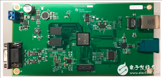
Figure 2. Reference design TIDA-01425 outline drawing Reference design TIDA-01425 main system indicators:
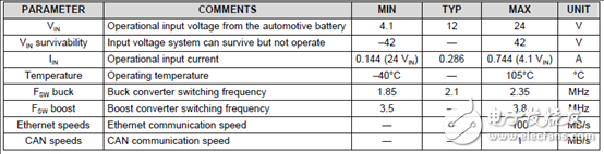
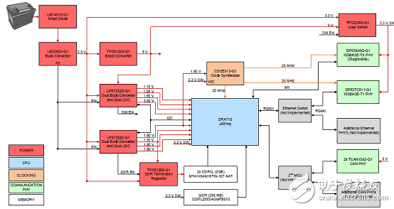
Figure 3. Reference Design TIDA-01425 Block Diagram
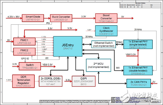
Figure 4. Reference Design TIDA-01425 Circuit Diagram (1)
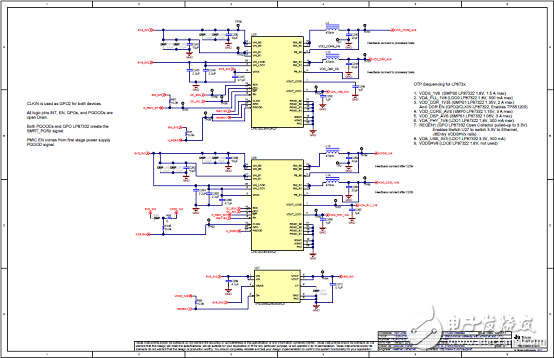
Figure 5. Reference Design TIDA-01425 Circuit Diagram (2)
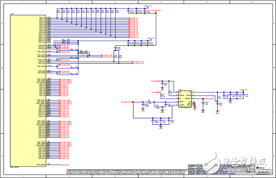
Figure 6. Reference Design TIDA-01425 Circuit Diagram (3)
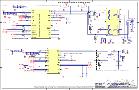
Figure 7. Reference Design TIDA-01425 Circuit Diagram (4)
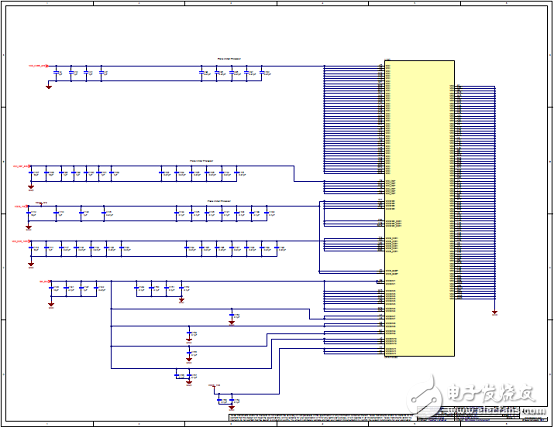
Figure 8. Reference Design TIDA-01425 Circuit Diagram (5)
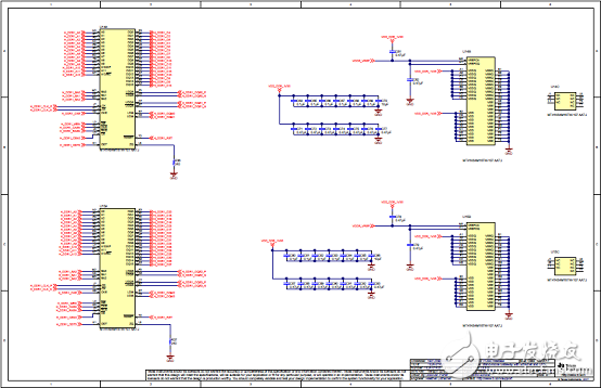
Figure 9. Reference Design TIDA-01425 Circuit Diagram (6)
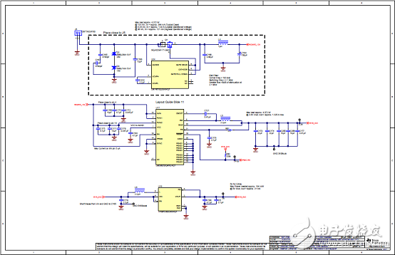
Figure 10. Reference Design TIDA-01425 Circuit Diagram (7)
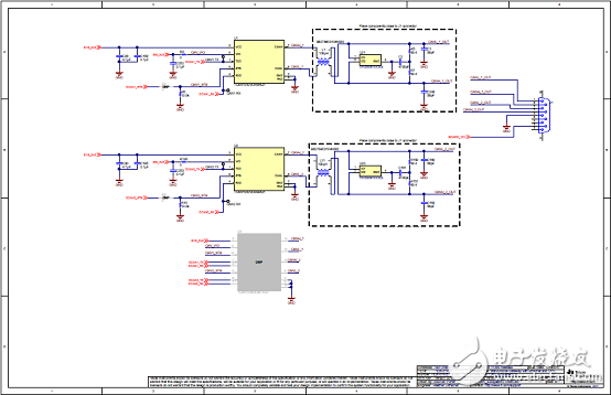
Figure 11. Reference Design TIDA-01425 Circuit Diagram (8)
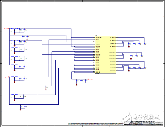
Figure 12. Reference Design TIDA-01425 Circuit Diagram (9)
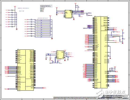
Figure 13. Reference Design TIDA-01425 Circuit Diagram (10)
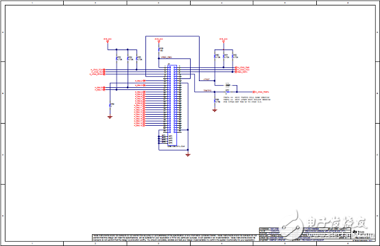
Figure 14. Reference Design TIDA-01425 Circuit Diagram (11)
Refer to the design TIDA-01425 bill of materials:
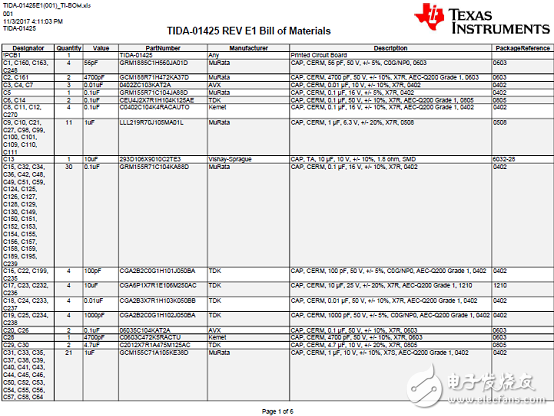
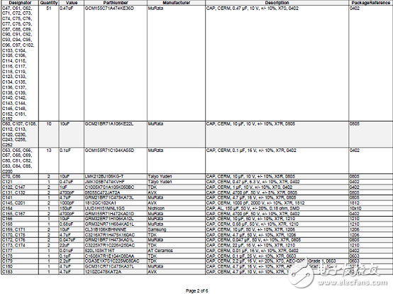
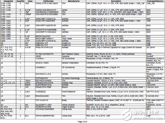
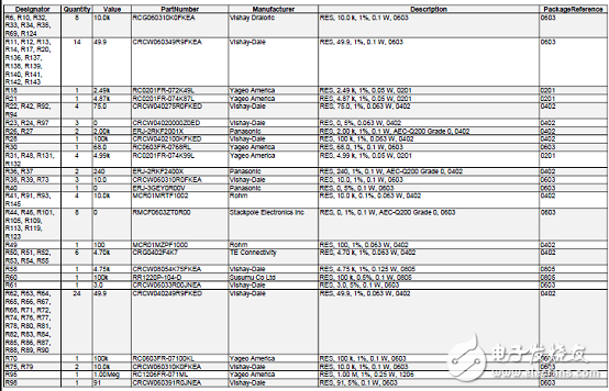
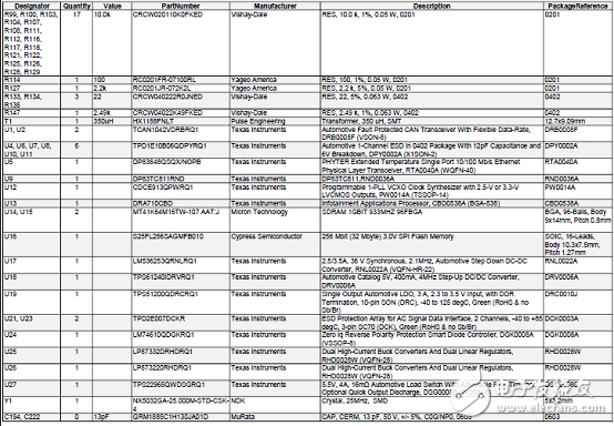
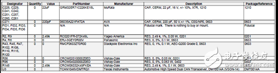
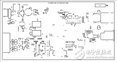
Figure 15. Reference Design TIDA-01425 PCB Design Drawing (1)
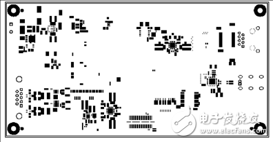
Figure 16. Reference Design TIDA-01425 PCB Design Drawing (2)
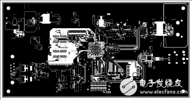
Figure 17. Reference Design TIDA-01425 PCB Design Drawing (3)
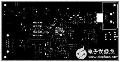
Figure 18. Reference Design TIDA-01425 PCB Design Drawing (4)
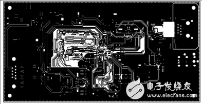
Figure 19. Reference Design TIDA-01425 PCB Design Drawing (5)
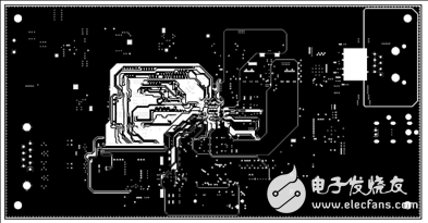
Figure 20. Reference Design TIDA-01425 PCB Design Drawing (6)
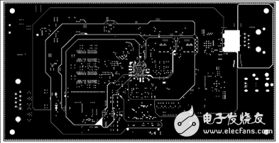
Figure 21. Reference Design TIDA-01425 PCB Design Drawing (7)
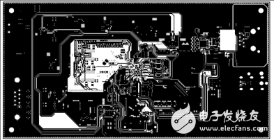
Figure 22. Reference Design TIDA-01425 PCB Design Drawing (8)
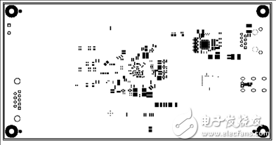
Figure 23. Reference Design TIDA-01425 PCB Design Drawing (9)
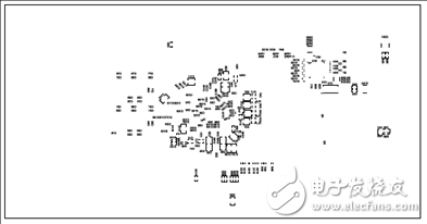
Figure 24. Reference Design TIDA-01425 PCB Design Drawing (10)
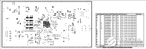
Figure 25. Reference Design TIDA-01425 PCB Design Drawing (11)
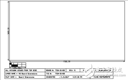
Figure 26. Reference Design TIDA-01425 PCB Design Drawing (12)
Easy Electronic Technology Co.,Ltd , https://www.yxpcelectronicgroups.com