
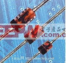
The Zener diode can be thought of as part of the diode set by listening to the name. Yes, he is the unbreakable part of the diode. Let us dial the true face of it and see how it relates to the ordinary diode.
Zener diode working principle - voltage regulation principle
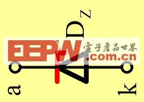
What is a Zener Diode ? A Zener Diode (also known as a Zener Diode) whose circuit symbol is as above. A Zener diode is a single PN junction diode used to stabilize voltage. This diode is a semiconductor device that has a very high resistance until the critical reverse breakdown voltage. At this critical breakdown point, the reverse resistance is reduced to a small value. In this low resistance region, the current increases and the voltage remains constant. The Zener diode is binned according to the breakdown voltage. The Zener diode is mainly used as a voltage regulator or voltage reference component. As a result, engineers have created more regulators of regulated voltage for market demand.
Zener diode working principle - volt-ampere characteristics
The Zener diode works by using the voltage regulation characteristic of the reverse hit multi-zone. Therefore, the Zener diode is connected in reverse polarity with the power supply voltage in the circuit. The reverse breakdown voltage of the Zener diode is called the stable voltage. The stable voltage of different types of Zener diodes is also different. The voltage regulation value of a certain type of Zener diode is fixed in the range of the mouth. For example, the regulation value of 2CW11 is 3.2 volts to 4.5 volts, where the regulation value of one tube may be 3.5 volts, and the other tube may be 4, 2 volts.
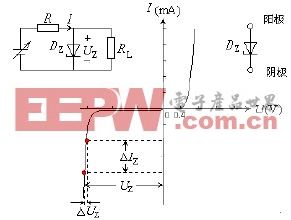
The quality of the Zener can be expressed by the dynamic resistance r:
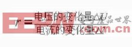
It can be seen from the above equation that the change in the dynamic resistance r is determined by the change in current when the amount of voltage change is constant. The larger the operating current is, the smaller the dynamic resistance r is. In order to make the voltage regulation effect better in the actual circuit, the pursuit of large operating current makes the dynamic resistance small. However, it must not exceed the maximum allowable current of the tube.
In practical applications, if the regulator voltage is not selected to meet the required voltage regulator, a regulator tube with a lower regulation voltage can be selected, and then several silicon diode "pillow pads" can be connected in series to increase the stable voltage to the required value. . This is achieved by using a silicon diode with a forward voltage drop of 0.6 to 0.7 volts. However, such diodes must be connected in the forward direction of the circuit, which is different from when the regulator is used. The forward voltage of the Zener diode is determined by the material at the time of manufacture, which is 0.3V, and the silicon tube is 0.7V.
It can be seen from the figure that the Zener diode is not much different from the ordinary diode, and the working area is different, and the manufacturing process is also different. In the temperature characteristics, the Zener diode and the ordinary diode are also affected by a large temperature.
Zener diode working principle - identification and detection
There are all kinds of diodes around us. How do we find the Zener diodes from many diodes?
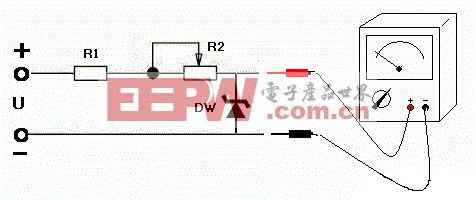
As shown below: For a Zener diode with a regulation voltage less than 20V, R1 takes 3.3k R2 to take 10K, and the power supply voltage takes 24V. The multimeter is placed in 10V or 50V position. Slowly adjust R2 When the voltage to be measured is less than the voltage regulation voltage, the reverse impedance of the voltage regulator diode is very large, almost no current flows, and the multimeter voltage reading slowly rises. When the voltage to be measured is greater than the voltage regulation voltage, the voltage regulator II The reverse impedance of the polar body is very small and becomes a breakdown state. At this time, the multimeter voltage reading suddenly drops, and the voltage regulator reads the highest voltage before the sudden drop of the voltage, which is the steady voltage regulator voltage value, and also determines that it is Zener diode.
Zener diode working principle - main parameters
1) Stable voltage Uz
The stable voltage is the operating voltage of the Zener diode in the reverse breakdown region and the voltage across the tube. This value varies slightly with the operating current and temperature. Even with the same type of Zener diode, the stable voltage value has a certain dispersion. For example, the stable voltage of the 2CW14 silicon Zener diode is 6 to 7.5V.
2) Dissipated power Pz
When the reverse current passes through the PN junction of the Zener diode, a certain power loss is generated and the temperature of the PN junction will also rise. The dissipated power of the tube is determined based on the allowable PN junction operating temperature. Usually small power tubes are on the order of a few hundred milliwatts to a few watts. Maximum Dissipated Power Pzm: The maximum power loss of the Zener diode depends on the area of ​​the PN junction and heat dissipation. In reverse operation, the power loss of the PN junction is: Pz = Vz * Iz, and Izmax can be determined by Pzm and Vz.
3) Stable current Iz
Minimum stable current Izmin, large stable current Izmax stable current: reverse current when the working voltage is equal to the stable voltage; minimum stable current: minimum reverse current required when the Zener diode operates at a stable voltage; maximum stable current: Zener diode The maximum reverse current allowed to pass.
The dynamic resistor rz has the same concept as the dynamic resistance of a typical diode, except that the dynamic resistance of the Zener diode is derived from its inverse characteristics. The smaller the rz, the steeper the breakdown characteristics of the Zener tube. Rz=â–³Vz/â–³Iz
4) Temperature coefficient
The change in temperature will cause VZ to change. In the Zener diode, when |VZ| > 7V, Vz has a positive temperature coefficient and reverse breakdown is avalanche breakdown. When |Vz| < 4V, VZ has a negative temperature coefficient and reverse breakdown is Zener breakdown.
When 4V
The working principle of the Zener diode - the difference from the diode
First: the diode generally operates under a forward voltage, and the Zener diode operates in a reverse breakdown state, and the usage is different;
Second: the reverse breakdown voltage of common diodes is generally above 40V, high can reach several hundred volts to thousands of volts, and the reverse breakdown of the volt-ampere characteristic curve is not steep, that is, the range of reverse breakdown voltage. Larger, dynamic resistance is also larger. For a Zener, when the reverse voltage exceeds its operating voltage Vz (also known as Zener or regulated voltage), the reverse current will suddenly increase and the voltage across the device will remain essentially constant. The corresponding reverse volt-ampere characteristic curve is very steep and the dynamic resistance is small. The Zener can be used as a voltage regulator, voltage reference, overvoltage protection, level shifter, etc. This book uses the ZD symbol to indicate the voltage regulator.
Zener diode working principle - application
1. Surge protection circuit: The Zener tube breaks down under the correct voltage, which makes it usable as a limiting or protective component. Because various voltage Zener diodes are available, it is especially suitable for this application. suitable. The Zener diode D is used as an overvoltage protection device. As long as the power supply voltage VS exceeds the diode's regulated value D, it is turned on, so that the relay J pulls the load RL apart from the power supply.

2. Overvoltage protection circuit in the TV: EC is the main supply voltage of the TV. When the EC voltage is too high, D is turned on, and the transistor BG is turned on, and its collector potential will be changed from the original high level (5V) to the low level, and the television enters the standby protection state by the control of the standby control line.
3. Arc suppression circuit: When a suitable Zener diode is connected in parallel on the inductor coil (it can also be connected to a common diode), when the coil is turned off in the conduction state, it is generated due to the release of electromagnetic energy. The high voltage is absorbed by the diode, so when the switch is turned off, the arc of the switch is eliminated. This application circuit is used more in the industry, such as some higher power electromagnetic control circuits.
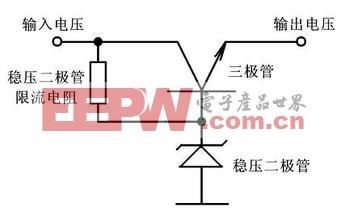
4. Series regulator circuit: In this circuit, the base of the series regulator BG is clamped at 13V by the Zener diode D, then the emitter outputs a constant 12V voltage. This circuit is used in many situations.
Zener diode working principle - precautions
Zener diodes are versatile and extremely versatile. It seems that the application is very simple, but if you don't pay attention, it is extremely vulnerable. The following are some notes on the selection:
1: Multiple Zener diodes can be used in series, but they cannot be used in parallel because of the large discreteness of the diode parameters.
2: Temperature has a great influence on the characteristics of semiconductor devices. When the ambient temperature exceeds 50 °C, the maximum dissipation power should be reduced by 1% for every 1 °C increase in temperature.
3: The Zener diode pin must be soldered at a distance of more than 5 mm from the tube, preferably using a soldering iron of 30 W or less. If soldering with 40~75W soldering iron is used, the soldering time should not exceed 8~10s. Use solder wire soldering with solder as much as possible. Do not use large solder and rosin.
4: In order to compensate the voltage temperature coefficient of the Zener diode, the Zener diode can be used in series with a silicon diode (including a silicon Zener diode). The string of forward diodes must not exceed three, and can also be combined with special temperature compensation. The tubes are used in series.
Zener diode
An electrical appliance used to protect electrical equipment from high transient overvoltage hazards and to limit the duration of continuous flow.This term includes any external clearance necessary for the normal functioning of the appliance during operation and installation, whether or not it is a unit as a whole.
Surge protector, also known as lightning arrester, is an electronic device that provides safety protection for all kinds of electronic equipment, instruments and communication lines.When the electric circuit or communication lines or for outside disturbance suddenly produce peak current in voltage, surge protector in a very short time conduction tap, to avoid surge damage to other devices in the circuits.[1]
Surge protector, suitable for ac 50/60 hz, rated voltage 220 v to 380 v power supply system, the indirect lightning and thunder and lightning directly affect transient over voltage surge protection, or other applicable to the family home, the third industry and the surge protection industry requirements.
Surge Protector,Surge Voltage Protector,Eco-Friendly Surge Protector,Lightning Protection Surge Protector
YANGZHOU POSITIONING TECH CO., LTD. , https://www.pst-thyristor.com