
introduction
This article refers to the address: http://
The embedded monitoring system consisting of image acquisition and storage functions is an indispensable part of the security technology system. With the development of microelectronic technology and software technology, embedded technology has also made great progress. Therefore, the image data acquisition and storage monitoring system based on embedded technology is widely used in many occasions because of its intuitive, convenient and rich information content.
The monitoring system works in a specific environment and has very special environmental and structural requirements, which puts high requirements on the hardware and software platform of the monitoring system. The performance of the processor is improved, the ability of the interface to transmit data is enhanced, especially in the future, the appearance of high-capacity memory, the miniaturization and multi-function of the image monitoring system are easy to implement. After the embedded technology is introduced into the image monitoring system, two problems need to be solved. The solution is a flexible image monitoring system structure adjustment, and the second is an interactive software design suitable for monitoring specifications, integrating image and signal detection and control.
1 System platform construction
1.1 Construction of the hardware platform
ARM (AdvancedRISCMachines) can be considered as the name of a company, or as a general term for a type of microprocessor, and can also be considered as a technical name.
The S3C2410 processor is a 32-bit microcontroller based on ARM's ARM920T processor core and 0.18um manufacturing process from Samsung. The processor has: independent 16KB instruction cache and 16KB data cache, MMU, TFT controller supporting TFT, NAND flash controller, 3 UART, 4 DMA, 4 Timer with PWM, I/O port, RTC , 8-channel 10-bit ADC, TouchScreen interface, IIC-BUS interface, IIS-BUS interface, 2 USB hosts, 1 USB device, SD host and MMC interface, 2 SPI. The S3C2410 processor can run at up to 203MHz.
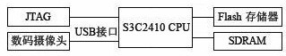
The hardware structure of the image acquisition system with S3C2410 as the core is shown in Figure 1. Because there is only a small amount of memory inside the S3C2410, I have to expand the memory of the system. As a 32-bit microprocessor, the S3C2410 supports 8-bit, 16-bit and 32-bit addressing modes with 16M×32-bit addressing capability. It is convenient to construct a large storage space, and the system memory is composed of FLASH and SDRAM. The digital camera is connected to the S3C2410 chip through the USB interface, and the S3C2410 chip is used to control the digital camera to collect images and store them in the memory.
1.2 Construction of the software platform
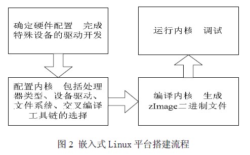
Embedded Linux (EmbeddedLinux) refers to a dedicated Linux operating system that can be used in specific embedded applications after being miniaturized by Linux and can be solidified in a memory or a single-chip microcomputer. The specific construction process is shown in Figure 2.
2 USB camera device driver development
In the Linux kernel source directory, driver/usb/usb_skeleton.c provides a basic USB driver, which we call the USB skeleton. By simply modifying a few parts, you can complete the drive of a USB device. Our USB driver development also started from it. The USB driver structure is as follows:
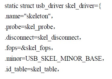
This structure indicates the work to be done by the USB device driver. The details are as follows:
(1) When the driver module is loaded, register with the USB core subsystem and tell the subsystem that the device needs to be supported.
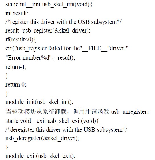
(2) Log out of the USB core subsystem when uninstalling the USB device driver.
(3) Which functions are called when a supported device is inserted or removed.
In the initialization function, the USB device driver calls the usb_register function to register.
The above describes the framework of a simple USB device driver. But the camera driver development we are going to do is slightly more complicated than the above driver. In addition to the previously mentioned USB driver, it also includes a device driver for the image acquisition section.
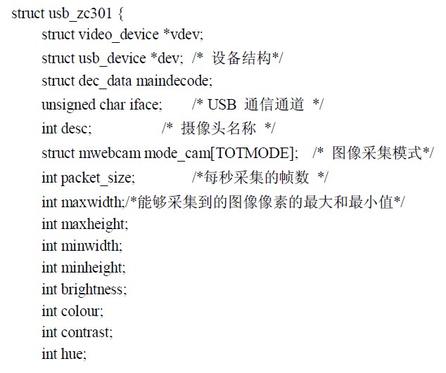
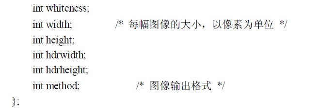
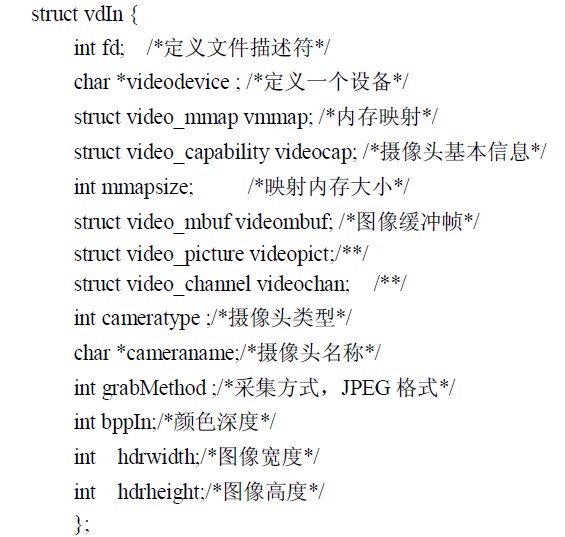
First, we need to define a data structure, one of which includes image information, acquisition mode, and decoding mode. The specific definition is as follows.
The first thing the LinuxUSB driver needs to do is register it in the LinuxUSB subsystem and provide some information, such as which device the driver supports, and what actions will be taken when the supported device is plugged in or unplugged from the system. . All of this information will be transferred to the USB subsystem. The following code completes the registration function of the USB camera:
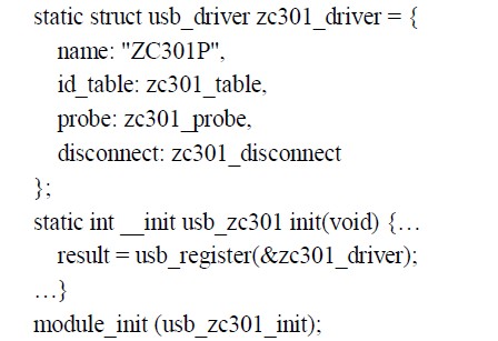
The meaning of the data defined above is as follows ZC301 is the name of the client driver to avoid repeated installation and uninstallation of the driver.
Zc301_probe points to the probe function pointer of the USB driver, and provides a function to the USB kernel to determine whether the driver can drive an interface of the device.
Zc301_disconnect Pointer to the disconnect function in the USB driver that will be called by the USB core when removed from the system or when the driver is being unloaded from the USB core.
The zc301_table list contains a list of all the different types of USB devices that the driver can support. If the list is not set, the probe callback function in the driver will not be called.
When the system starts up, it first needs to load various drive modules, and then register the manufacturer number (VendorID) and product number (Pro-ductID) with the system. When the USB device is connected to the host, the system will detect its VendorID and ProductID. If it matches the registration content of the driver module, the driver will be attached to the device [5]. When the camera is inserted, the system calls the zc301_probe function. The parameter dev specifies the device information, the probe function verifies the validity of all optional configurations, and calls the sbvideo_Regis-terVideoDevice() function of the usbvideo module to register with the videodev system.
After the system completes the driver registration, the staticintzc301_init(structusb_zc301*zc301) and staticvoidzc301_start(structusb_301*zc301) functions are called to complete the initialization process of the device: fill in the register values ​​and start the camera. The system runs to this step, basically completes the camera driver loading and device initialization. Next, you need to read the user-set image specifications, including: image format, resolution, color depth, contrast, and brightness. The reading of these values ​​is achieved by the following functions:
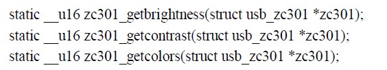
After getting these parameter values, call a set of functions to set the parameters. Each parameter setting function has a one-to-one correspondence with the previous parameter value function. The specific function is as follows:
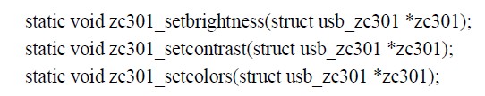
By calling the above function, we basically get the required parameter values, so we can start the camera.
Of course, we also need staticvoidzc301_shutdown(structusb_zc301*zc301) to turn off the camera.
At this point, the drive of the camera drive is basically completed. Through the setting of these functions, we can abstract the specific hardware circuit into the parameter values ​​in the data structure. Next, we can call these functions through the V4L driver to implement a series of processes such as assigning parameters, opening devices, capturing images, and shutting down devices.
When recompiling and running the kernel, the USB camera driver will be successfully loaded in the serial feedback. As shown in Figure 3.
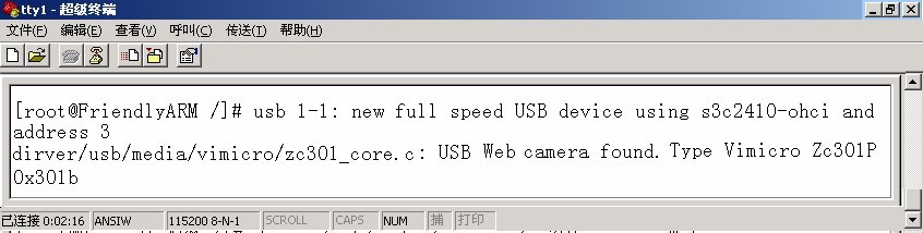
Figure 3 serial port feedback information 3Video4Linux image acquisition programming:
Video4Linux, or V4L for short, is a kernel driver for video devices in Linux that provides a series of semi-standard interfaces for application programming for video devices. V4L uses this interface to add some extra features while providing an API of its own. We can implement various functions by calling the V4L API. Under Linux, the normal use of video capture devices relies on support for the Video4Linux standard. The current V4L covers video and audio stream capture and processing, and the USB camera is also supported by it.
The main data structure defined in V4L:
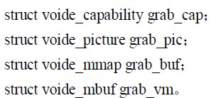
These data structures are supported by Video4Linux and their uses are as follows:
(1) video_capability contains the basic information of the camera, such as the device name, the maximum supported minimum resolution, the source information, etc., corresponding to the member variables in the structure, name maxmax, maxheight, minwidth, minheight, channels (number of sources) ), type, etc.
(2) voide_picture contains various attributes of the device to capture images, such as brightness, hue, contrast, whiteness, depth, etc.
(3) video_mmap is used for memory mapping;
(4) The frame information mapped by voido_mbuf using mmap is actually the frame information input into the camera memory buffer, including size (frame size), frames (maximum number of supported frames), offsets (relative base address per frame) Offset).
Before the system acquires images, it is necessary to initialize the parameter values ​​in these data structures, and the system can collect image data as required.
After the USB camera is driven, you only need to write another application for video streaming. According to the characteristics of embedded system development, first write the application on the host machine, then use the cross compiler to compile the link and generate the executable file on the target platform. The host communicates with the target board by means of a printing terminal for cross-commissioning, and successfully migrates to the target platform.
V4L image acquisition programming process:
(1) Opening the video device;
(2) reading device information;
(3) Change the current settings of the device;
(4) Video acquisition to obtain image information;
(5) processing the collected image;
(6) Turn off the video device.
This article writes the acquisition program on the host PC installed Linux operating system, and then transplanted to the development board. The following is a specific discussion.
Earlier we talked about the main data structures and their functions defined in V4L. Corresponding to this content, we need to define these data structures to abstract a video device. The following are specific definitions:
Camera, image capture, and camera off. The following functions are defined in the acquisition program to implement the functions mentioned above.
intinit_videoIn(structvdIn*vd, char*device, intwidth, intheight, intgrabmethod); Initializes the camera device. *vd contains basic information from the previously defined data structure. In addition, it is necessary to assign values ​​such as the size of the image captured by the camera and the acquisition mode.
intv4lGrab (structvdIn * vd, char * filename); acquisition image main program. *filename is the file name of the image. We can determine the location where the image is saved by setting the file name.
Intclose_v4l (structvdIn * vd); Close the camera intget_jpegsize (unsigned char * buf, intinsize); the size of the captured image.
Because we collect and save the image by calling the main function intv4lGrab(structvdIn*vd, char*filename), we need to explain the composition of the function in detail. The following is the specific content of the function:
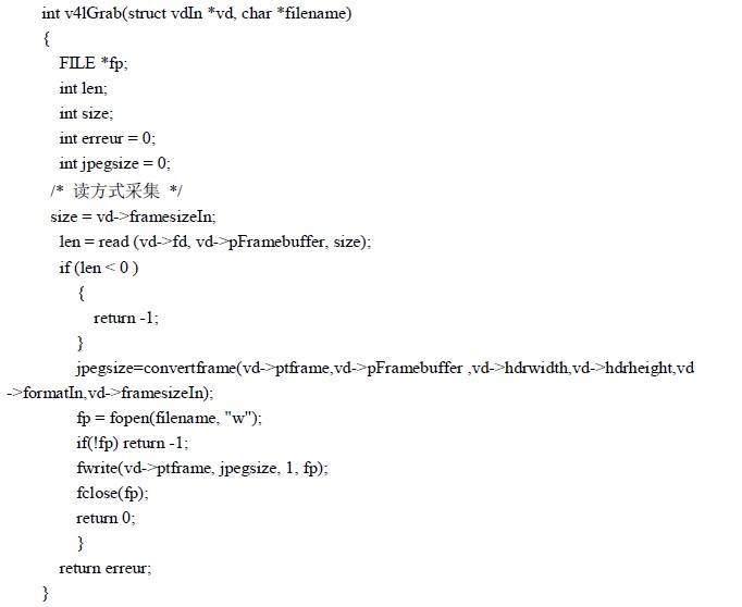
First, we need to define several parameters, as follows:
FILE*fp; defines a file type pointer to the image file intlen we collected;
Define an integer variable to record the amount of data read from memory, intsize;
Define an integer variable that specifies the amount of data for an image of image interreur=0; define an integer variable that specifies the runtime return value intjpegsize; defines an integer variable that indicates the size of the image we need.
Then we call the read(vd->fd,vd->pFramebuffer,size) function to read the data stored in the image buffer into the specified temporary file. Then we convert the image data collected before the image size, brightness, contrast, etc., and finally we open a file, write the image data to the file and save it.
4 Conclusion
In this paper, an embedded video acquisition system is designed. The system is compact and realizes the image acquisition, storage and reproduction functions of the system when the current information is complete and the storage capacity is occupied as little as possible. In hardware planning, a simple and practical USB interface is used for communication. And a rich peripheral interface is reserved in the system, which is convenient for future expansion and upgrade.
SHAOXING COLORBEE PLASTIC CO.,LTD , https://www.fantaicolorbee.com