![]() The PIC32MZEF has a total of six UART ports, and the resources are quite rich. UART is a commonly used peripheral, especially when debugging, the serial port print information is very convenient, it is very convenient to test, this will test the transmission and interrupt reception of UART data.
The PIC32MZEF has a total of six UART ports, and the resources are quite rich. UART is a commonly used peripheral, especially when debugging, the serial port print information is very convenient, it is very convenient to test, this will test the transmission and interrupt reception of UART data.
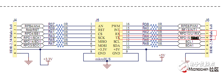
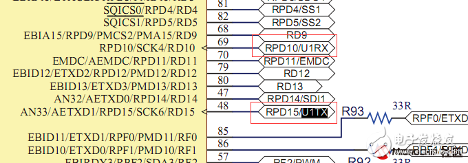
First look at the pin interface in the board schematic, UART1 and UART2 are brought out to the connector, but the UART2 pin is used as an OLED driver, let's test UART1.
The main features of the UART module are:
• Full-duplex 8-bit or 9-bit data transmission
• Even parity, odd parity or no parity option (for 8-bit data)
• One or two stop bits
• Hardware auto-baud rate feature
• Hardware flow control options
• Fully integrated Baud Rate Generator (BRG) with 16-bit prescaler
• Baud rate range from 76 bps to 25 Mbps (PBCLK2) at 100 MHz
• 8-level deep first-in-first-out (FIFO) transmit data buffer
• 8-level deep FIFO receive data buffer
• Parity, frame and buffer overflow error detection
• Support for interrupts only during address detection (9th bit = 1)
• Independent send and receive interrupts
• Loopback mode for diagnostic support
• LIN protocol support
• IrDA encoder and decoder with 16x baud clock output for external IrDA encoder/decoder
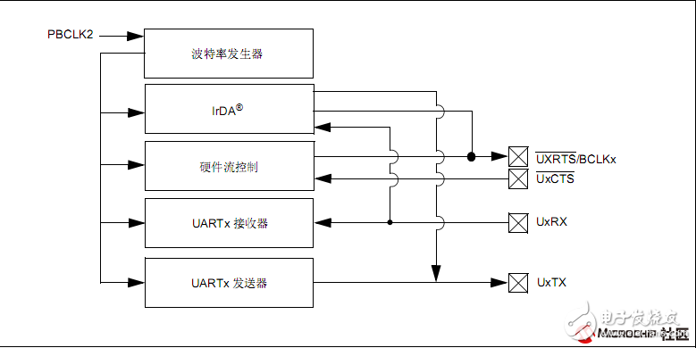
Let’s take a look at the internal block diagram of
The following details the configuration of the UART. Open the MHC and open the HarmonyFramework Configuration "Drivers" USART. Check the box in the selection box before “Use USARTDrive?â€. Enable UART peripheral functions.
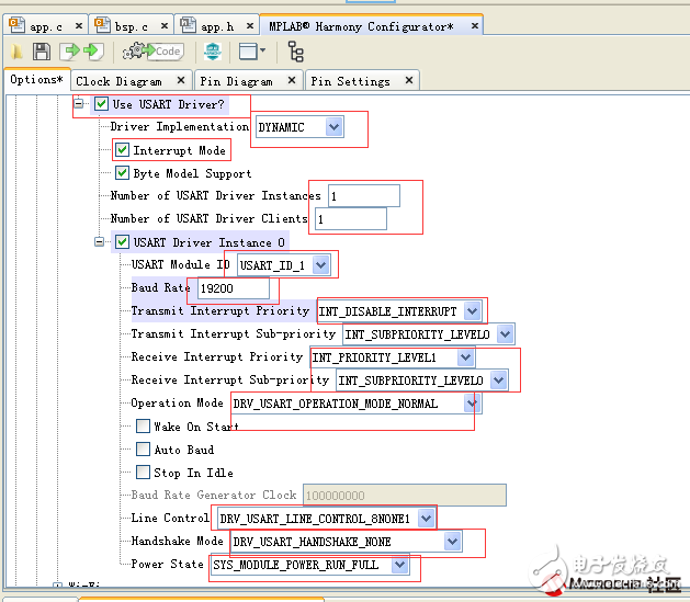
1, Driver Implementation: This is dynamic and static, we choose dynamic here.
2. Interrupt mode selection is enabled. Check here to enable interrupt.
3, Number of USART Driver Instances: Select the number of USART instances required. According to the number in the "Number of USART Driver Instances" dialog box, "USARTDriver Instance N" (N = 0, 1, 2...) will be generated.
Expand "USART Driver Instance N" (N = 0, 1, 2...) to configure the static drivers for each USART instance as needed for your application.
4, USART Module ID: Select ID1, which is the UART1 used, here you can choose 1-6.
5, Buad Rate: baud rate setting, here we set to 19200
6, send the interrupt priority setting, send me generally use the query mode, and receive the use interrupt mode, so here send the option to disable the interrupt.
7, receive interrupt priority settings, InterruptPriority and Interrupt Sub-priority are the choice of interrupt priority. Each vector has 7 user-selectable priorities, and each user has 4 user-selectable sub-priorities.
8, Operation Mode: mode selection, mode has IrDA mode, normal mode, address detection mode, loopback mode. We can choose the normal mode.
9, Line Control: data format selection, data bits have 8, 9 bits, check has odd parity, even parity, no parity, stop bits have 1, 2 bits. We choose the N81 data format.
10, Handshake Mode: Handshake mode, there are simplex mode, flow control mode and normal mode. We choose the normal mode.
11, Power State: used to select which energy-saving mode the UART can run. Here, selecting FULL means that all modes can be run.
Open the pin setting window, make 48, 69 two pin settings, set to UART pin


Click Generate Code to choose to automatically overwrite the previous program.
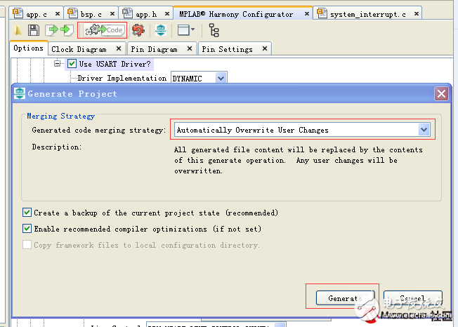
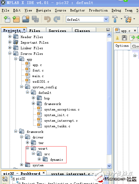
Read the new project file after the build
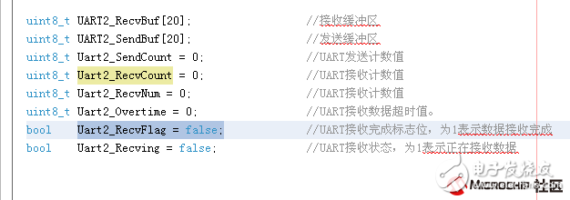
Add some variable definitions to the APP.H file
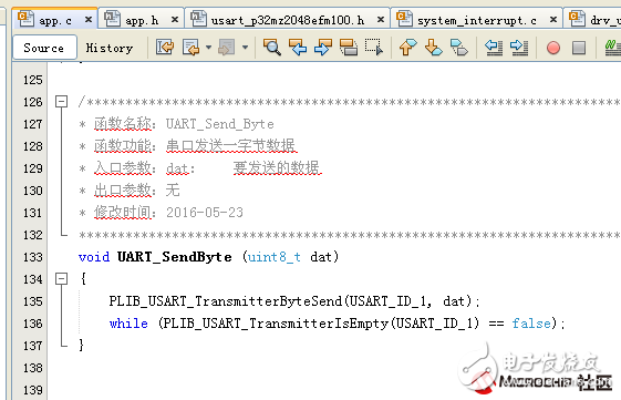
Or move the interrupt function directly to APP.C and write the program. In the next article, I will introduce how to use the callback function to write the program. Add functions, programs in App.c. The program immediately sends back a byte of data and displays the number of bytes received on the display.
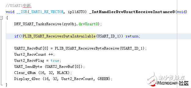
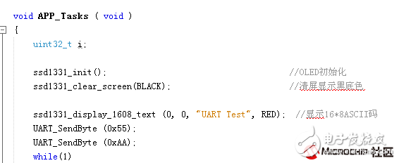
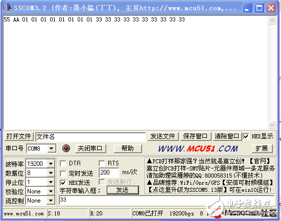
PC test software, send a 55, AA after power-on
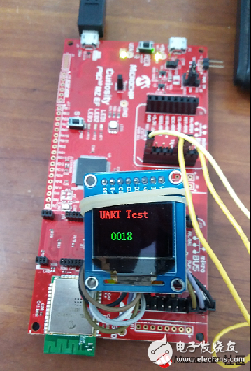
Display effect and hardware wiring, directly use TTL to USB adapter
Fractional horsepower centrifugal switches
Fractional Horsepower Motor,Fractional Horsepower Ac Motor,3 Phase Starter Switch,Auto Motor Starter Switch
Ningbo Zhenhai Rongda Electrical Appliance Co., Ltd. , https://www.centrifugalswitch.com
