A stepper motor is an electromechanical component that converts an electrical pulse signal into an angular displacement or a linear displacement. The input of the stepping motor is a pulse sequence, and the output is the corresponding incremental displacement or stepping motion. In normal motion, it has a fixed number of steps per revolution; when performing continuous stepping motion, its rotational speed maintains a strict correspondence with the frequency of the input pulse, and is not affected by voltage fluctuations and load changes. Since the stepping motor can directly accept digital control, it is particularly suitable to use a microcomputer for control.
(1) Types of stepper motors
There are currently three types of stepper motors:
(1) Reactive stepping motor (VR) reactive stepping motor has a simple structure, low production cost, and small step angle; but the dynamic performance is poor.
(2) Permanent magnet stepping motor (PM) permanent magnet stepping motor has large output and good dynamic performance; however, the step angle is large.
(3) Hybrid stepping motor (HB) hybrid stepping motor combines two reactive and permanent magnet stepping motors
The advantage of the step is that it has small step angle, large output and good dynamic performance, and is the highest performance stepping motor at present. It is sometimes referred to as a permanent magnet induction stepper motor.
(two) working principle of stepper motor
Figure X1 Schematic diagram of three-phase reactive stepping motor
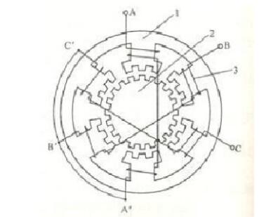
1——stator 2——rotor 3——stator winding
Figure x1 is a schematic cross-sectional view of the most common three-phase reactive stepper motor. There are six even magnetic poles on the stator of the motor with an angle of 60o. The coils are sleeved on each of the magnetic poles, and connected to the A, B, and C three-phase windings according to FIG. 40 small teeth are evenly distributed on the rotor. Therefore, the pitch of each tooth is θE=360o/40=9o, and there are also 5 small teeth on the pole arc of each pole of the stator, and the pitch and tooth width of the stator and the rotor are the same. Since the number of small teeth of the stator and the rotor are 30 and 40, respectively, the ratio is a fraction, which results in a so-called tooth misalignment. If the small teeth of the A-phase magnetic poles are aligned with the small teeth of the rotor, as shown in the figure, the teeth of the B-phase and C-phase magnetic poles are respectively one-third of the pitch of the rotor teeth, that is, 3o. Therefore, the magnetic resistance at the B and C poles is larger than the magnetic resistance at the A magnetic pole. If the phase B is energized, the phase B winding generates a stator magnetic field whose magnetic line passes through the phase B magnetic pole and tries to close according to the path with the smallest magnetic resistance, which causes the rotor to rotate by the reaction torque (reluctance torque) until The teeth on the B pole are aligned with the rotor teeth, just as the rotor turns 3o; at this time, the teeth under the magnetic poles of A and C are respectively shifted by one-third of the pitch from the rotor teeth. Then, the B-phase winding is stopped, and the C-phase winding is energized. Similarly, the rotor is rotated by 3o in the clockwise direction due to the reaction torque.
Similarly, when the three-phase winding is energized in the order of A→B→C→A, the rotor will rotate in a clockwise direction with a regular step of 3o for each energizing pulse. If the power-on sequence is changed, the power is cycled in the order of A→C→B→A, and the rotor rotates in a counterclockwise direction with a rotation of 3o for each energizing pulse. Because only one phase winding is energized at each moment, and the power is cycled in three energization states, it is called a single three-shot operation mode. The step angle θb of the single three-shot operation is 30o. The three-phase stepping motor also has two power-on modes, which are respectively two-three-beat operation, that is, the mode of circulating power according to AB→BC→CA→AB, and the single and double six-shot operation, that is, pressing A→AB→B → BC → C → CA → A sequential cycle power supply. The step angle of the six-shot operation will be reduced by half. The step angle of the reactive stepper motor can be calculated as follows:
Θb=360o/NEr(x-1)
In the formula, Er—the number of rotor teeth, N—the number of running shots, N=km, m is the number of winding phases of the stepping motor, k=1 or 2.
(3) Characteristics of stepper motor
(1) The stepping motor must be driven to operate. The drive signal must be a pulse signal. When there is no pulse signal, the stepper motor is stationary. If an appropriate pulse signal is added, it will be at a certain angle (called the step angle). Turn. The speed of rotation is proportional to the frequency of the pulse.
(2) The stepping motor has the superior characteristics of instant start and rapid stop. (3) Changing the order of the pulses makes it easy to change the direction of rotation.
L298n drive motor worksWorking principle analysis:
In the stepping motor drive module, TLP521 with optocoupler isolation and strong anti-interference ability is adopted as the isolated current protection chip, wherein the 17th leg of L297 controls the forward and reverse of the stepping motor by giving high and low level, and 18 feet For the stepping clock input terminal, control the time increment of each step, the half-step or the whole step of the 19-step stepping motor is selected, and the 10-pin is the enabling control terminal to control the start and stop of the motor, and the inner contains 4 Channel logic drive circuit, high voltage, high current double H bridge driver L298 to control the motor's forward and reverse; use L298 to realize motor drive and its forward and reverse, and use diode for freewheel protection, use 7805 to provide 5v power supply to controller And l298 chip power supply, this circuit is prone to heat in the case of long working hours, resulting in circuit instability.
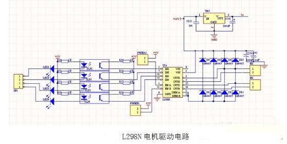
The main features are:
Key chip: L298N double H bridge DC / stepper motor driver chip
L298N chip working voltage: DC 4.5~5.5V.
Motor drive power supply voltage DC 5--35V.
LED indicator is indicated when the power input is normal.
PCB size: 4.4*5.0cm
The maximum output current is 2A (instantaneous peak current 3A) and the maximum output power is 25W.
When the output is normal, the motor is running with an LED indicator.
With diode freewheel protection.
Two DC motors or one two-phase 4-wire (or 6-wire) stepper motor can be controlled separately.
A DC motor up to 3A can be controlled by a parallel connection method.
The motor can be reversed.
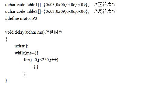
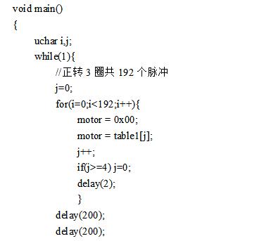
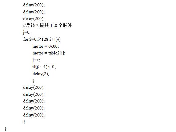
L298N drive stepper motor program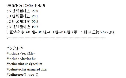
Zinc wire is a good anti-corrosion material,widely used in steel structure anti-corrosion,wind power tower,bridge,sluice gate,oil pipe on sea,Ductile iron pipe,extrusion division tube.
|
|
Zinc Wire,High Pure Zinc Wire,Zinc Wire Mesh,Corrosion Protection Zinc Wire
Shaoxing Tianlong Tin Materials Co.,Ltd. , https://www.tianlongspray.com
