
The resolver contains three windings, one rotor winding and two stator windings. The rotor winding rotates with the motor, the stator windings are fixed and the two stators are at an angle of 90 degrees to each other (as shown in Figure 1). In this way, the winding forms a transformer with an angle-dependent coefficient.
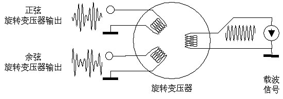
Figure 1: Resolver and related signals
A sinusoidal carrier applied to the rotor winding is coupled to the stator windings and the stator winding output is angularly dependent on the rotor winding for amplitude modulation. Due to the mounting position, the phase difference between the modulated output signals of the two stator windings is 90 degrees.
The angle position information of the motor can be obtained by demodulating two signals. First, a pure sine wave and a cosine wave are received, and then the tangent value of the angle is obtained by division. Finally, an angle value is obtained by an “arctangent†function. Since the DSP is generally used for arithmetic processing, the sine and cosine waves need to be digitized. There are several specialized products on the market with these features, but they are expensive and require alternatives for most applications.
One of the most common methods currently used is to detect the peak of the carrier frequency in the output signal to trigger an analog-to-digital converter (ADC). If the modulation signal is always switched at this point in time, the carrier frequency will be cancelled. Since higher-resolution delta-sigma (delta-∑) ADCs always sample the signal over a period of time, it will not only convert the peak voltage, so it is necessary to use successive approximation ADCs such as the TI ADS7861 or ADS8361 to resolve The rate is also limited to 12-14.
This method also requires the use of several circuit blocks, which must generate a suitable sinusoidal carrier. The conversion process must be triggered at a suitable point in time and the ADC must convert the signal synchronously. This not only increases costs, but also has limited resolution.
The theoretical basis of the new concept
The new concept uses an oversampling method and shifts the demodulation into the digital domain. The oversampling of the modulation signal uses the ADS1205 dual-channel delta sigma modulator and the digital filter chip AMC1210 is used for demodulation and decimation of the modulator output.
The modulator produces only a bit stream, which is different from the digital concept in the ADC. In order to output a digital signal equivalent to the analog input voltage, a digital filter must be used to process the bit stream. A sine filter is a filter that is very simple, easy to build, and requires minimal hardware.
Those signals whose frequencies are integer multiples of the value of the modulator clock frequency divided by the oversampling rate will be suppressed. These suppressed frequency points are called notches. In this new concept, the decimator's decimation rate is set so that the carrier frequency falls within a notch frequency. But first the signal needs to be demodulated, otherwise the angle information will be ignored along with the carrier frequency. This task is completed by AMC1210.
The AMC1210 has four channels, each with a filter structure as shown in Figure 2.

Figure 2: The digital filter structure of the AMC1210
The AMC1210 can also be used to measure current. In this example, we use a comparator filter for over-current protection and can achieve fast response at low resolution (shown in blue in the figure). The yellow part produces a higher resolution output at lower sample rates, which is used for the control loop. According to the needs of the application, a sine filter and integrator can be used here to optimize the structure of the filter. In addition, this path can also be used for filtering and demodulation.
First, the sine filter in the AMC1210 filters the modulator's bit stream to convert it to a medium-resolution, medium-rate data word. For the ADS1205, the oversampling ratio (OSR) of the most efficient third-order sine filter is 128. When the oversampling rate exceeds 128, the OSR doubles and the signal-to-noise ratio increases by only 3dB. Using the integrator after the demodulation process can achieve the same effect, but also reduce the filter delay time.
Setting the OSR to 128 produces a 14-bit digital modulation signal with a data rate of:
In this equation, fmod represents the modulator's clock frequency, which is reduced by half in the modulator. In the following example, when the frequency of the clock signal is 32.768 MHz, the data rate of the third-order sine filter is 128 kHz.
Armored tape is generally a metal band or metal shell wrapped around the surface of the device to protect the power cable from wear or corrosion.
For example, armored cables are wrapped with a layer of copper tape outside the cable to prevent being pierced or worn by sharp objects,it can provide flexible Cord Covers.
Armoured thermocouple is the thermocouple jacket with stainless steel jacket to prevent internal corrosion of the thermocouple.
As Electrical Cord Covers Supplier,CAS Applied Chemistry Materials Co.,Ltd.is famous
as:
1. Provided products for the State Grid in 2008 to ensure the smooth progress
of the Beijing Olympic Games.
2. Provided products and services to China Southern Power Grid in 2010 to
ensure the smooth progress of the Guangzhou Asian Games.
3. Occupied more than 50% of insulation protection field of overhead contact
line for China High Speed Rail Market.
4. has been Excellent supplier and long-term partner of Aviation Industry
Corporation of China.
5. Provided core technology and products for power cable accessories
(electrical stress control).
Armoring Tape,Flexible Cord Covers,Electrical Cord Covers,Rubber Floor Cable Protector
CAS Applied Chemistry Materials Co.,Ltd. , https://www.casac1997.com