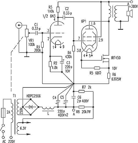
The circuit has the following characteristics: 1. The use of block building blocks can be appropriately increased or decreased according to their own economic conditions. 2. The voltage amplifying part and the current amplifying part are separately designed and laid out, which is convenient for fans to use two sets of high and low voltage power supplies for power supply, and can choose a variety of characteristic back-end circuit collocations. It is also convenient to install fixed heat sinks to provide convenience for enthusiasts. 3. The use of no-loop negative feedback design can further improve the effect of speaker negative feedback electromotive force on sound quality.
Due to space limitations, the voltage amplifying part and current amplifying part are introduced here. The following are two-channel design, only one channel schematic is given, the other channel, power supply and protection circuit diagram are omitted.
1. Voltage amplification part
Use the finished board provided by the manufacturer. The two-channel design of the board is made of double-sided gold-plated circuit board. A large number of fever devices are used on the board, such as five-ring metal film resistors, ELNA fever capacitors, high-frequency tubes for audio, and field effect tubes for low-noise constant current sources. The principle diagram is shown in Figure 2. The use of twin field effect transistor NPD5565 input, using common source common base circuit, active load and differential circuit, compared with Marantz company's HDAM module circuit and voltage amplification module circuit produced by some domestic manufacturers, the design of this circuit seems more inclined The voltage amplifying board has a wide range of adaptability to the power supply, and can work from ± 35V to ± 60V. It is recommended that the voltage amplifying part be powered by a parallel stabilized power supply, and the voltage of the current amplifying part is 5V to 10V higher. Perfect, sound quality is more ideal.
Second, the current amplification part
There are a variety of current amplifier boards that can be used with the above voltage amplifier boards. The following table lists some parameters of the power tube used for audiophiles.
1.2SKSK2013 / 2SJ313 pushes 3 pairs of 2SK1529 / J200, the schematic diagram is shown in Figure 3.
2.2 SK2013 / 2SJ313 pushes 3 pairs of 2SC5200 / 2SA1943, the schematic diagram is abbreviated, please refer to Figure 3, only need to change K1529 / J200 to C5200 / A1943 during assembly.
3.2 SC5171 / 2SA1930 promotes 6 2SK851, the schematic diagram is shown in Figure 4, the super-large current MOS field effect tube 2SK851 has the characteristics of fast switching speed, small on-resistance and low distortion rate. There is still no field effect tube paired with it. This circuit uses the form of quasi-complementary output. 2SK851 was used in Tianlong PWA-2000N power amplifier.
4.2 SC5171 / 2SA1930 push 6 2SD1037, the schematic diagram is abbreviated, you can refer to Figure 4, when assembling, just replace K851 with D1037. The circuit uses a quasi-complementary output. As long as it is properly designed, the quasi-complementary output circuit can also produce beautiful sound. For example, the highly praised LM3886 and LM4766 use quasi-complementary output circuits.
5. Adopt 3 pairs of Sanken composite pipes SAP15N, SAP15P, the schematic diagram is shown in Figure 5.
6.2SK2013 / 2SJ313 promotes 8 pairs of high-power field effect transistors or triodes (figure omitted), which is convenient for enthusiasts to produce 100W × 2 pure class A.
3. Commissioning
The above 6 kinds of post-stage circuits can calculate the required Class A power or last-stage quiescent current according to P A = 2I02RL, so as to debug the last-stage quiescent current as needed. If a pure Class A machine with an output power of 80W under an 8Ω load has a final static current of Io = 2.236, then the static current flowing through each tube is Io ′ = Io / n = 2.236 / 3A = 0 745A, that is, the DC voltage drop across the 0.25Ω / 5W resistor is V = Io '? R = 745 × 0.25 ≈ 186 (Mv).
Although the pure Class A amplifier has a soft and sweet sound, it has extremely strict requirements on transformers, filter capacitors, power tubes and heat sinks. After listening for a month, the electricity bill is heavily burdened. In this case, enthusiasts may wish to make the amplifier into a high-bias Class A and B amplifier. For example, below 20W is a Class A output, and 20W to 100W is a Class A and B output. At this time, the total static circuit of the power amplifier is Io = 1.118A. In fact, in the general living room environment, the pure Class A output of about 20W can meet the listening requirements of most fans.
Since the voltage amplification part has been debugged by the manufacturer, only the final stage current amplification part and related interfaces need to be assembled. Fine-tune W1 of the voltage amplifying part to make the output be 0mV, and then adjust the multi-turn potentiometer W2 of the current amplifying part to measure the DC voltage across the 0.25Ω / 5W resistor to make it meet your own requirements. For Figures 3 and 4, you can directly Measure the voltage across 0.25Ω / 5W. For Figure 5, the voltage across the sap15N ④, ⑤ pin or sAP15P ①, ② pin should be measured.
If the test is normal, you can burn the machine for 1 to 2 hours, and check the parameters repeatedly. If it is correct, you can listen to the audio. If you want to assemble a pure Class A power amplifier, you can first adjust the whole machine to a high-bias Class A and B power amplifier, listen to normal, and then gradually increase the static current to the required value to make the machine a pure Class A power amplifier.
The above five kinds of current amplifier boards, the size of the equipped radiators are 360mm × 120mm × 50mm, the finished boards are debugged into high-offset Class A and Class B power amplifiers (Class 20W + 20W), if you want to assemble 80W + 80W pure Class A power amplifiers, just replace For the heat sink, install the power amplifier board into the professional radiator amplifier chassis (480mm × 430mm × 150mm) exposed on both sides.
The above lines can be used for multiple purposes by making minor adjustments (such as changing the transformer power and supply voltage, power tube logarithm and quiescent current). Such as: making high-power amplifiers (250W / 4Ω); making electronic crossover power amplifiers; making high-quality headphone amplifiers (using this voltage amplifier board to drive K214 / J77 or K2013 / J313); using voltage amplifying parts for middle and low-end components The power amplifier is used for motoring; the top 8-channel pure post-stage power amplifier is produced (such as using 4 voltage amplification boards, sharing power, and a pair of three Ken 2SC 3858, 2 SA 1494 per channel, etc.).

Follow WeChat

Download Audiophile APP

Follow the audiophile class
related suggestion
The principle of the field effect tube to control the working current is completely different from that of ordinary transistors, which is much simpler than ordinary transistors.

The five-pole power amplifier tube FD422 is used to make a single-ended Class A power amplifier. The design of this circuit is based on the principle of "simpleness first", which can reduce installation errors. Follow first ...

845 single-ended Class A amplifier circuit diagram will be 6N8P
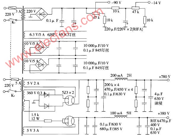
What is a pure Class A amplifier The so-called Class A or pure Class A amplifier is actually two sub-classes of the power amplifier classified by static operating point. According to this division, ...
Field effect tube characteristics and the artistic charm and evaluation of the production of audio amplifiers with single-ended Class A amplifiers Audio amplifiers can be divided into electronic ...
Single-ended Class A power amplifier circuit Below, we introduce a single-ended pure ...
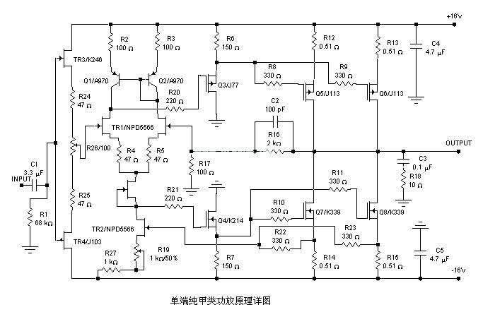
A 20W single-ended pure class A power amplifier circuit diagram, the circuit is very simple, used yuan ...
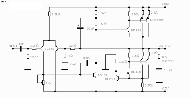
Circuit characteristics 1. This power amplifier uses a current negative feedback circuit (Japan's famous golden voice most power amplifier ...
The power amplifier made with the voltage regulator set is a pioneering idea for electronics enthusiasts ...
![[Photo] NE5532 20W pure class A amplifier driven in parallel](http://i.bosscdn.com/blog/20/06/41/5131158379.jpg)
This is a Class A power amplifier with an output power of 18W. The final stage uses a current series negative feedback circuit (the bypass capacitors at both ends of the output stage self-sufficient bias resistor are cancelled) ...
