
Digital oscilloscopes are an indispensable tool for designing, manufacturing, and servicing electronic devices. With the rapid development of technology and market demand, engineers need the best tools to quickly and accurately solve the measurement challenges they face. As an engineer's eye, digital oscilloscopes are critical to meeting the current tough measurement challenges.
Digital oscilloscopes have become increasingly popular due to their unique advantages such as waveform triggering, storage, display, measurement, and waveform data analysis and processing. Due to the large performance difference between digital oscilloscopes and analog oscilloscopes, if used improperly, large measurement errors will occur, which will affect the test task.
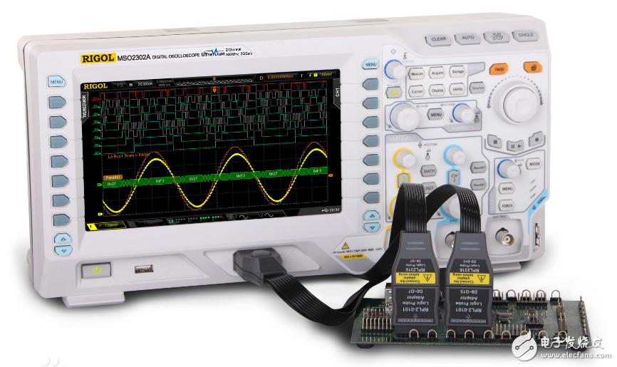
Digital oscilloscopes are high-performance oscilloscopes manufactured by a series of technologies such as data acquisition, A/D conversion, and software programming. The digital oscilloscope works by converting the measured voltage into digital information through an analog converter (ADC). The digital oscilloscope captures a series of samples of the waveform and stores the samples. The storage limit is to determine whether the accumulated samples can draw the waveform. Then, the digital oscilloscope reconstructs the waveform. Digital oscilloscopes can be divided into digital storage oscilloscopes (DSO), digital phosphor oscilloscopes (DPO) and sampling oscilloscopes.
The oscilloscope uses the steps to display and measure the DC signal (step)Turn on the power from the DC regulated power supply from the DC voltage of 10V, press any key to exit the self-test screen.
The input terminal ch1 of the oscilloscope is connected with a DC stabilized power supply by adding a signal line. (The ground wire of the input terminal ch1 of the oscilloscope is connected to the DC stabilized power supply ground wire) ï¬
Press the AUTO Auto Setup button
Press the UTILITY button and select the language as Chinese (Simplified)
Press the ACQUIRE button and select the acquisition method as the average value. The average number of times is 128.
Press the ch1 menu, select the grounding method for the coupling mode, adjust the position knob, and adjust the ground wire to the appropriate position. Adjust the volts/div to 5.00V/div (obviously marked), probe 1 & TImes;, inverting off.
Then select the DC mode for the coupling mode, and the line on the screen will jump up to 2 grids. (The ground wire needs to be clearly marked)
Turn on the power and press any key to exit the self-test screen.
Add the signal line to the input ch1 of the oscilloscope. (The ground wire of the input end of the oscilloscope is connected to the signal ground)
Press the auto-set button to press the ch1 menu, the coupling mode selects AC, adjusts the volts/division to 2.00V/div (obviously marked), the probe 1&TImes;, inverts off.
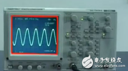
Press the TRIGGER menu and the source selects ch1 to adjust the trigger level to stabilize the waveform.
Press the MEASURE button to measure the frequency, period, peak-to-peak value of the signal, and select the ch1, and adjust the type to cycle, frequency, peak-to-peak, etc.
Press the CURSOR button, you can use the cursor to measure the voltage of the signal, select the voltage for the period type, move the position knob, place the cursor 1 at the upper end of the waveform, and place the cursor 2 at the lower end of the waveform, circle the increment number and change the type to time. Move the position knob to place cursor 1 at the left end of the waveform and cursor 2 at the right end of the waveform to circle the increment
Frame For Iphone,Metal Frame For Iphone,Series Frame With Glue,Frame For Iphone Xs
Shenzhen Xiangying touch photoelectric co., ltd. , https://www.starstp.com