
TETRA is a state-of-the-art PMR cellular communication system that has been successfully deployed worldwide. As TETRA networks grow, it is sometimes difficult for network administrators to ensure that network performance meets the high quality requirements of professional users. In the mature TETRA network, many people are constantly configuring the network. After the cell and cell clusters continue to increase, it is necessary to adjust the settings of some parameters in the parameters that define the TETRA behavior.
If TETRA users submit poor network performance to the wireless network management unit, most of these problems are related to the following three reasons:
1. Poor coverage or poor link budget results in poor connection quality, low availability, slow call setup or call interruption
2. Unable to provide service due to IOP (interoperability) issues
3. The adjacent channel configuration is poorly switchable, resulting in low availability or call interruption.
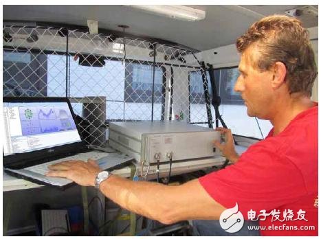
Figure 1: TETRA AirAnalyzer (Aeroflex) in the drive test car
Effective analysis tools help identify and resolve network configuration mismatch issues. At the same time, it helps to maintain the quality of network services to meet the higher requirements of professional users. Obviously, network operation without the TETRA air interface analyzer to periodically analyze service quality and performance can create various problems. This article describes how to do this analysis.
It is not enough to analyze by single path test.Downlink RF coverage is the most important quality of service (QoS) parameter. If the mobile station does not receive the base station signal, it cannot activate or enter the available state, and always maintains the scan mode for the remaining battery life. The first step in efficient network operation is to provide and maintain sufficient downlink RF coverage for the cellular network. In most cases, a road test receiver can be used for inspection, and a graphical display is used to verify that there is sufficient field strength within the specified limits of the required coverage.
Many network administrators believe that this kind of drive test is sufficient to detect RF coverage. However, the downlink coverage only provides one-way wireless connectivity. The link budget of the uplink between the mobile station transmitter (TX) and the base station receiver (RX) is as important as, or even more important than, sensitivity. Some networks increase the TX power of the base station if the user proposes or the network reception test has coverage problems (indicating poor radio frequency planning). The radio link operates in the downlink, and the opposite direction does not work because the TX power of the mobile station is much lower than that of the base station, thereby causing the radio cell to transmit too much power.
Problems similar to this can be found with the TETRA protocol analyzer. A mobile station that has a base station search problem increases the retry rate of the uplink before obtaining the notification information. Retrying the counter helps isolate problems with poor RF coverage in known areas.
One of the TETRA parameters (RXLEV_ACCESS_MIN) is defined for registration at the base station cell based on the mobile station RX level definition. This parameter is often set very low, such as â€115 dBm, so that the mobile station registers with the base station even when the RF level is low. Again, this parameter is sometimes used to detect poor RF planning. In an urban environment, this effect is very limited because the mobile station itself cannot efficiently search for a base station. The TETRA Network Analyzer's automatic parameter checking helps identify incorrect parameter settings, allowing users to simulate coverage during critical cell changes while performing a drive test.

Figure 2: Cell Change Analysis compares RXLEV_ACCESS_MIN with actual RX levels (Fjordâ€eâ€design)
3 improve the switching success rateSwitching is an important step in network operation and is very complicated. The seamless transition of a mobile station from one cell to another requires a large number of parameters to be calculated. If the switch fails during the call, a dropped call will occur. If the mobile station is idle, the handover failure will cause the mobile station to re-scan mode, resulting in a new registration. During the registration process, the mobile station cannot place or receive calls.
Good coverage, frequency planning and neighbor cell parameter planning are prerequisites for improving handover success rate. The Master Control Channel (MCCH) of the serving small area continuously broadcasts a group of neighboring cells (NCs) to all mobile stations. The Neighbor Cell (NCIE) contains the channel number (CN), the location area code (LA), and a number of related parameters for the supported services and NC configurations. The accuracy of NCIE is very important. When the network settings change, it needs to be updated to reflect the actual situation. Adjacent channel configuration mismatch or early or late will cause the above switching problem!
The first step is to check if the channel number of the physical neighbor cell matches the channel number published by the NCIE. Obviously, all MCCHs must activate NCIE. If the mobile station is switched from one cell to another, the new cell does not have an NCIE, and the mobile station loses the network connection and will leave the cell when the scan mode is resumed. The NCIE number should also match the actual situation. Some network operators choose an easy way to include all cells in the NCIE list. TETRA allows a cell to have up to 31 NCIEs, but this will result in the mobile station not registering with the neighboring NC and registering in the remote cell. Cells with the same frequency must not be adjacent and must be isolated in the NCIE definition. The more invalid signaling or handover failure will increase the load of the MCCH because the mobile station does not switch to the best cell.
The advanced TETRA network analyzer checks the consistency of the NCIE and displays a mismatch between the published information and the actual NC information. See Figure 3 for an example. The analyzer detects and displays that the published base station service does not match the actual service of channel 3794.

Figure 3: TETRA Network Analyzer Shows No. 7 Cell Mismatch (Aeroflex)
A similar problem can be observed when the base station broadcasts NC service and network load status error messages. The NCIE information broadcast by the serving cell is based on the NC itself. TETRA's ACCESS PARAMETER and RXLEV ACCESS MIN parameters are part of the C1/C2 level calculation and are the input values ​​that the mobile station determines to begin switching. If the settings in these NCIEs are different from those in the actual NC, the handover will fail, or the mobile station will have to make the next handover because the actual coverage is far worse than the published results. In extreme cases, a "ping-pong" switch occurs, ie the mobile station switches back and forth between the two cells. As a result, the quality of the service is poor, the call setup is slow, and the invalid signaling message causes the MCCH load to be very high.
Figure 4 shows the actual situation of the network, where the TETRA Packet Data (SNDCP) service is a standard feature that can be used continuously by the in-vehicle data terminal. Therefore, the SNDCP service should be available to all cells. In this case, the serving cell NCIE informs the NC that the SNDCP service can be used. However, when the mobile station switches, it obtains different messages in the new cell broadcast information. On the surface, the community does not support SNDCP, which can actually be supported. The mobile station suspends the data connection of this cell, and the vehicle terminal cannot work. In this case, the police often cannot download the information of the central registration system.
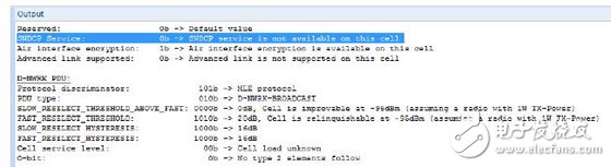
Figure 4: Detail view shows that grouping data is not supported - actual support (Aeroflex)
Interoperability problemTETRA device testing is primarily used to ensure interoperability between different vendor systems. However, a large part of the TETRA standard is undefined and there are dedicated add-on services not covered by the IOP process, which can cause problems in the field. At the same time, the base station and SwMI (switching and management infrastructure) and the old software version of the mobile station are also responsible for the incompatibility.
A good example is the TETRA EGâ€Mode (Energy Saving Mode), which extends the life of the mobile station battery by saving energy, but only for private networks. Using the TETRA protocol analyzer with a message sequence table (shown in Figure 5), it is easy to track the registration process of the mobile station (Brand A supports EGâ€Mode) at the base station (Brand B does not support EGâ€Mode). The base station notifies the PDU (Protocol Data Unit) EG-Mode request, but not its own request. The correct action is to confirm or reject the connection to the mobile station.
In an actual network, the base station ignores the request to connect to the cell. It is not possible for the mobile station to register in this cell. This type of analysis can only use protocol analyzers that support both uplink and downlink. With some protocol tracking software, it is impossible to obtain reliable results based on simple mobile stations.
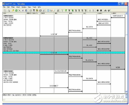
Figure 5: The message sequence table shows the TETRA protocol in detail (Aeroflex)
Is there any other detection function?
The base station is the most important part of the TETRA wireless network and requires regular maintenance. As with other technical systems, the performance of these network elements will slowly decline during 24 hours a day, 7 days a week. External effects such as static electricity and lightning flashes on the antenna can degrade the performance of the receiver. The base station maintenance test only needs to use the TETRA base station tester and can be completed in a few minutes. The advanced base station tester automatically detects the TRX module in one maintenance mode while the other TRX modules are still working. Therefore, there is no need to suspend the base station service, but the traffic is reduced during the detection process. This detection includes transmitter performance such as TX power, modulation vector error and frequency error, receiver sensitivity, checking TRX module operating conditions for compliance with TETRA specifications, and providing the best network service.
ConclusionThe examples described in this article are actual network operations, not simulations. We removed the network and country code from the example diagram, but these examples did reduce the quality of service for actual TETRA users. Using the right test equipment and simple QoS test procedures guarantees TETRA network quality and helps improve availability, thereby increasing professional wireless user satisfaction and communication efficiency.
Network Accessories, Network Products, Network Items, Network Equipment, Internet Accessories
Chinasky Electronics Co., Ltd. , https://www.chinacctvproducts.com