
Spartan-6 CMT is a flexible, high performance clock management module. It is located next to the center of the chip, perpendicular to the global clock network. As shown in Figure 2-17, it contains a PLL and two DCMs.
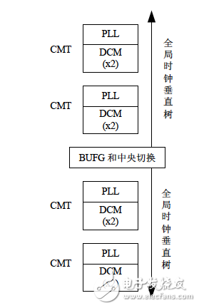
Figure 2-17 Spartan-6 FPGA CMT on-chip layout
First, DCMThe DCM in Spartan-6 is similar to that in Spartan-3, as shown in Figure 2-18, and is also composed of four parts.
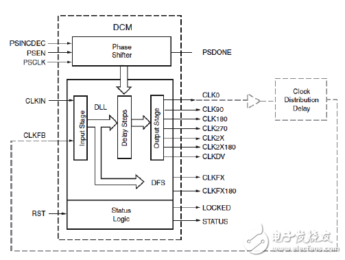
Figure 2-18 DCM function structure
(1) Delayed phase-locked loop (DLL).
The DLL delay-locked loop removes the DCC's output clock skew based on the input clock to completely eliminate clock skew. The principle is to compare the clock input (CLKIN) with a feedback input (CLKFB) and then control the delay line selector by adding the appropriate delay to the DLL path until CLKIN coincides with CLKFB.
The DLL input clocks are CLKIN and CLKFB, and the output clock signals are CLK0, CLK90, CLK180, CLK270, CLK2X, CLK2X180, and CLKDV.
(2) Digital Frequency Synthesizer (DFS).
The DFS has two user registers that set the multiplier (CLKFX_MULTIPLY) and crossover (CLKFX_DIVID) coefficients relative to the input clock (CLKIN). DFS can be used alone or in conjunction with a DLL; if DFS is not used with a DLL, there is no corresponding phase relationship between the CLKIN and DFS outputs. The output of DFS is CLKFX and CLKFX180.
(3) Phase shift unit (PS).
The input signals of the phase shift unit PS are PSINCDEC, PSEN, and PSCLK, and the output signals are PSDONE and STATUS[0]. The phase shift mode includes a fixed phase shift and a variable phase shift.
The fixed phase shift is the phase output of the DCM's 9 clocks, typically a fraction of the input clock period. The fixed phase shift value is set in the design and loaded into the FPGA during FPGA configuration.
In addition to the fixed phase shift, the PS also supports variable phase shifting, which dynamically changes the phase shift through the digital interface (PSINCDEC, PSEN, and PSCLK) according to system requirements. The phase shift value of each dynamically changed value is DCM_DELAY_STEP, and the range corresponding to DCM_DELAY_STEP can be referred to the "Spartan-6 Data Sheet" on the attached CD-ROM.
(4) Status logic.
The state logic reflects the state of the DCM and corresponds to the two output signals LOCKED and STATUS[0].
As shown in Figure 2-19, there are mainly two DCM primitive calls, DCM_SP and DCM_CLKGEN.
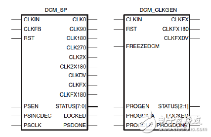
Figure 2-19 DCM primitive
DCM_SP provides the traditional features of DCM: clock DESKEW, frequency synthesis and fixed and variable phase shift.
All DCM_SP properties are determined at design time. When powering up, the program is programmed into the FPGA. Except for the dynamic phase shift function, all properties cannot be changed at runtime.
DCM_CLKGEN provides more DFS performance as follows.
Low jitter CLKFX and CLKFX180 outputs.
The jitter tolerance of the input clock CLKIN is increased.
Supports dynamic programming of M and D, dynamically setting CLKFX_MULTIPLY and CLKFX_DIVIDE.
The CLKFX_MULTIPLY and CLKFX_DIVIDE attribute values ​​have a larger range.
The self-excited oscillator operates when the input clock is lost.
With spread spectrum function.
Pay special attention to the characteristics and parameters of DCM_SP and DCM_CLKGEN in the design. Please refer to the Spartan-6 Clock Resource User Manual on the CD-ROM.
Magnetic Ring Inductors,High Current Manganese Zinc Toroidal Inductors,Manganese Zinc Magnetic Ring Inductor Power,Toroidal Plug-In Inductors
Shenzhen Sichuangge Magneto-electric Co. , Ltd , https://www.scginductor.com